>> Introduction / Content
To help you replace these parts several videos are available. These videos make it all look quite simple. But it took us much longer and we ran into several issues that are not shown on these videos. If you do this for the fist time, it can take several days:
- Steering-servo
- About taking out the spur, needed place the magnet
- There is a support video for the telemetry but this is more about the idea than about the problems we have to solve.
- This video about the replacement of the ESC is straightforward.
The above videos deal with just one subject. In our makeover we have to combine them.
And also, we don’t put back the receiver and the cooler.
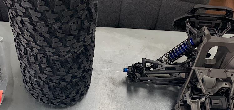
Lets go!
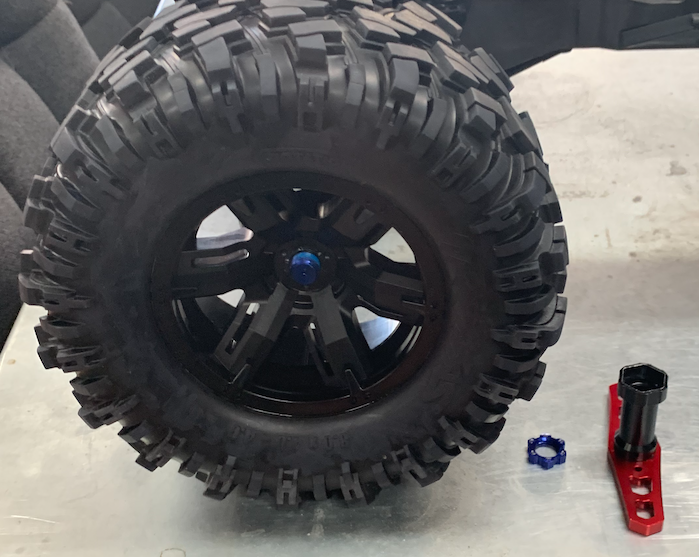
We took off the wheels.
The steering-servo

We start with the steering servo.
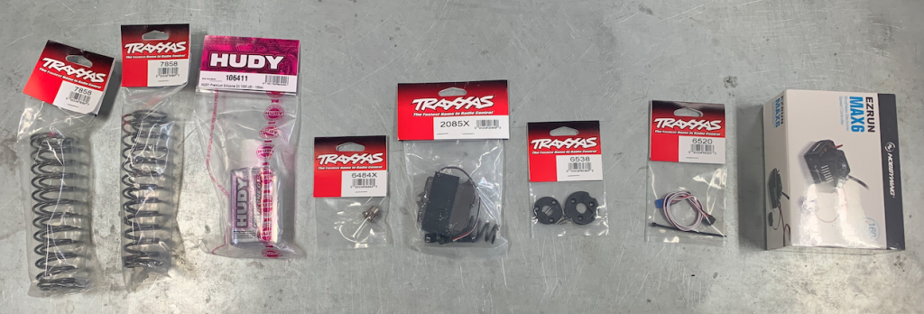
From the contents of the package we don’t use the spring and the steering linkage.
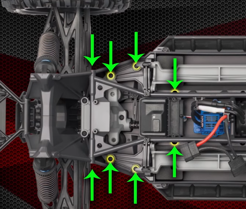
Remove the screw etc.
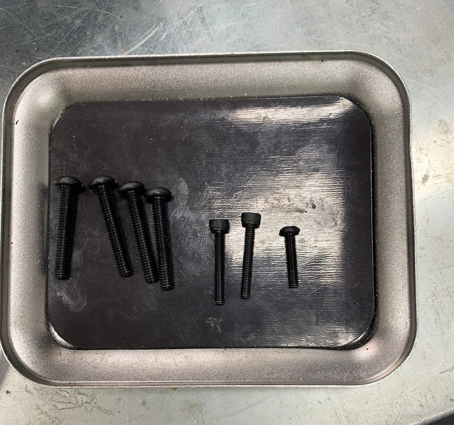
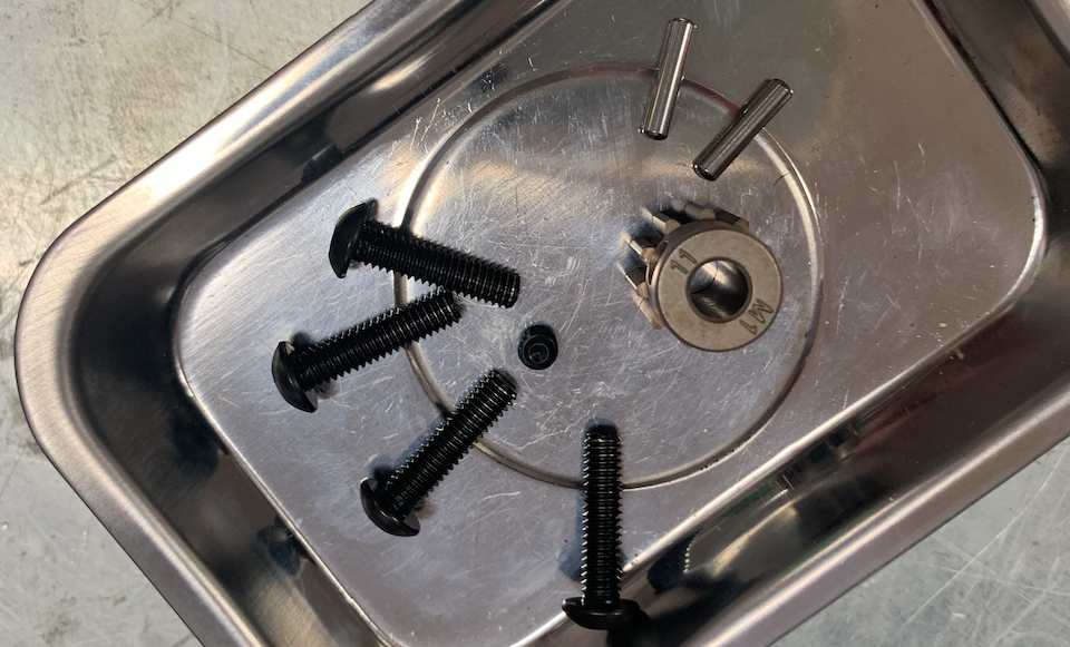
Collect the screws in a little tray
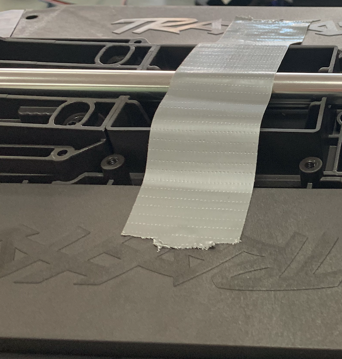
Follow the steering servo video until second 0:51.
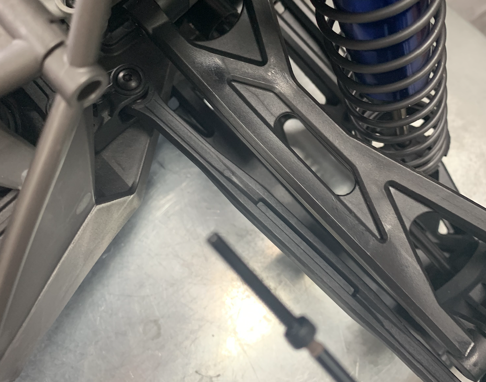
Don’t pull the front off.
First go to second 0:55 and remove the center skid plate
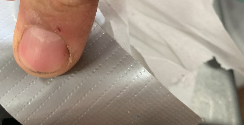
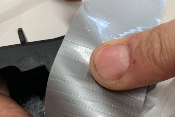
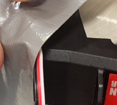
Stick the main axle with duct-tape to the back .
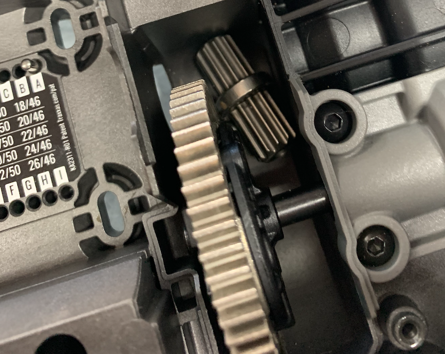
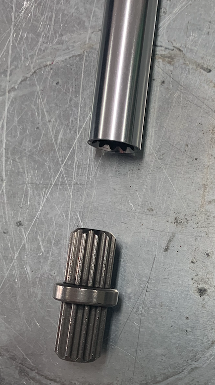
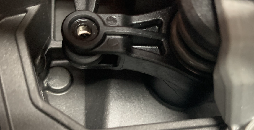
If the main axis is moving to much and the chassis is turned, the connector can drop into the gearbox.
If that happens you have to place it back and this wil take another hour.
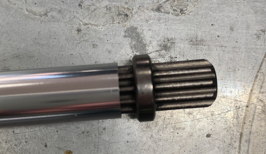
Let’s hope this doesn’t happen and you won’t recognise these pictures.
After sticking the axis to the chassis we continue with the video from second 0:51.
Follow the video until 1:25.
Then disconnect all wires from the receiver and take the antenne and the receiver out.
You can store these, we won’t put these back.

To disconnect the antenne, take out the little screw.

Don’t lose it.

Take the antenne carefully off the wire and put it aside.
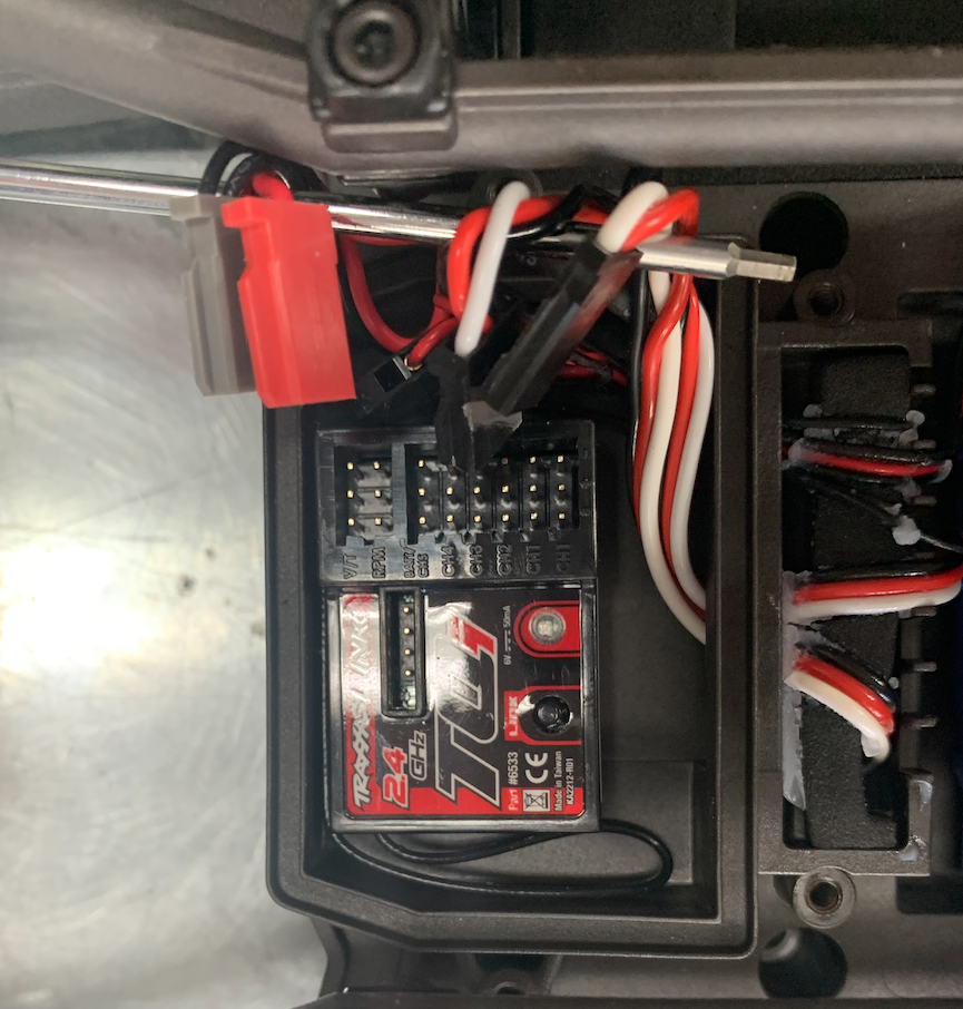
Pull all wires from the receiver.
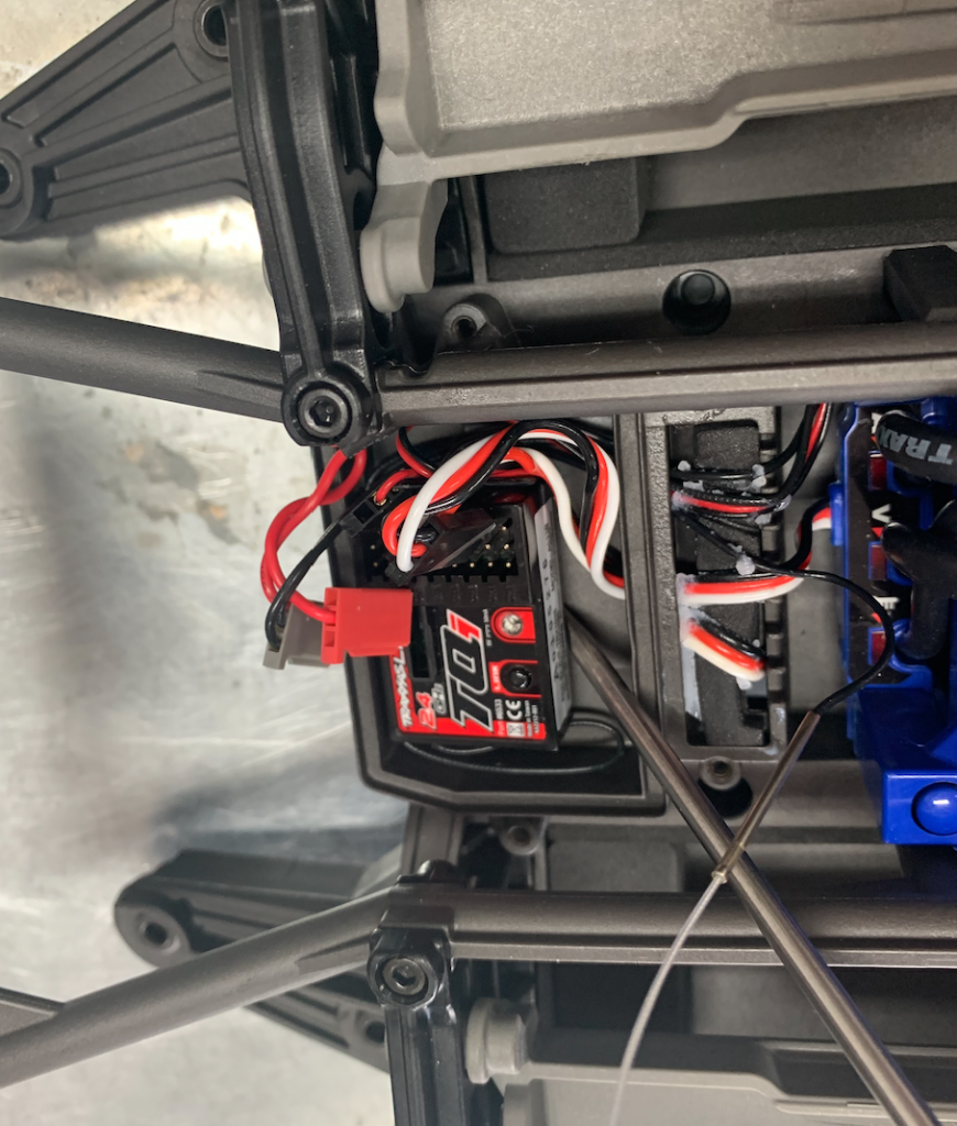
Take the receiver out.
If necessary, don’t hesitate to use the screwdriver.
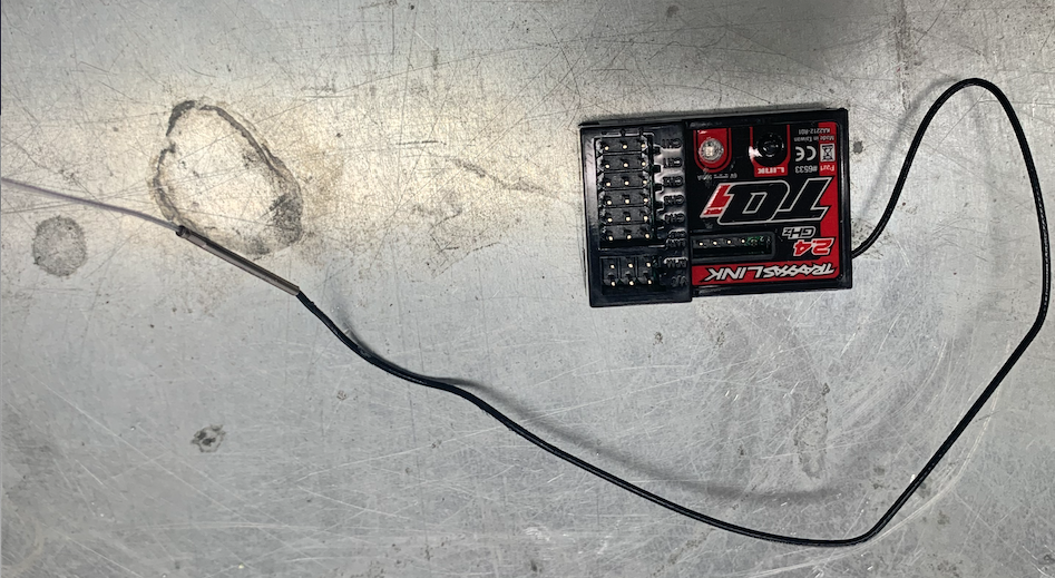
And put it aside.
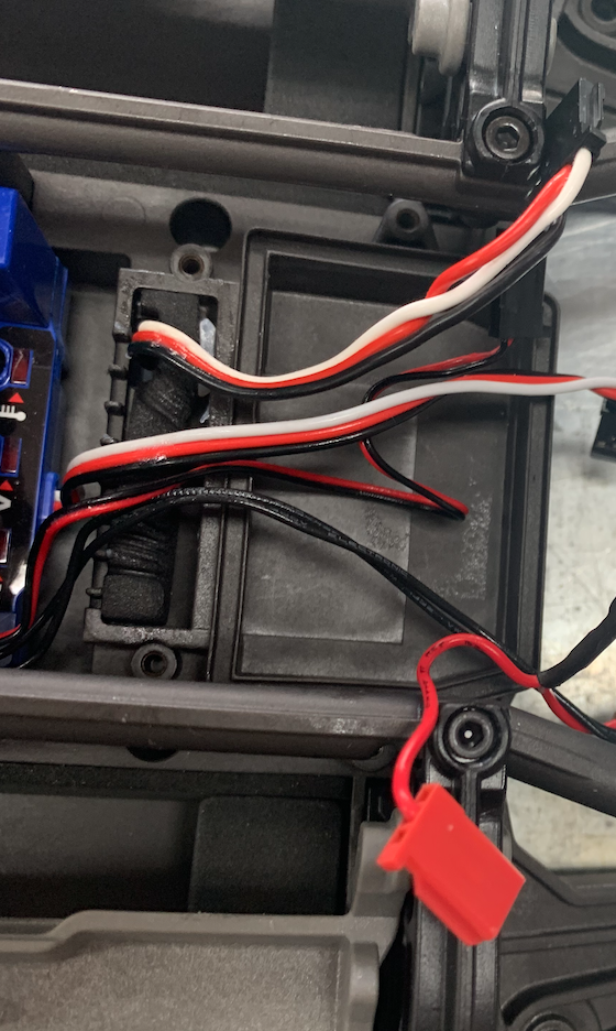
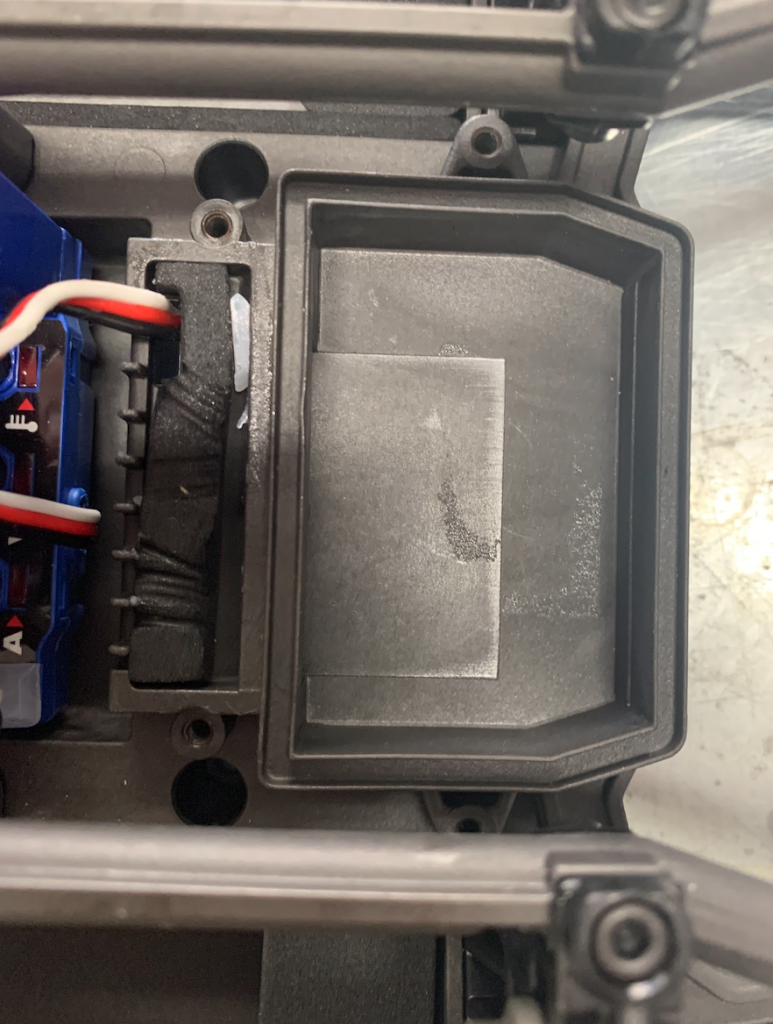
The place where the receiver was is empty and, although we put the cover back, wil stay empty.

Turn the chassis upside-down again.
Let’s change the steering servo.
Follow the instructions in the video from 1:28 to 1:48.
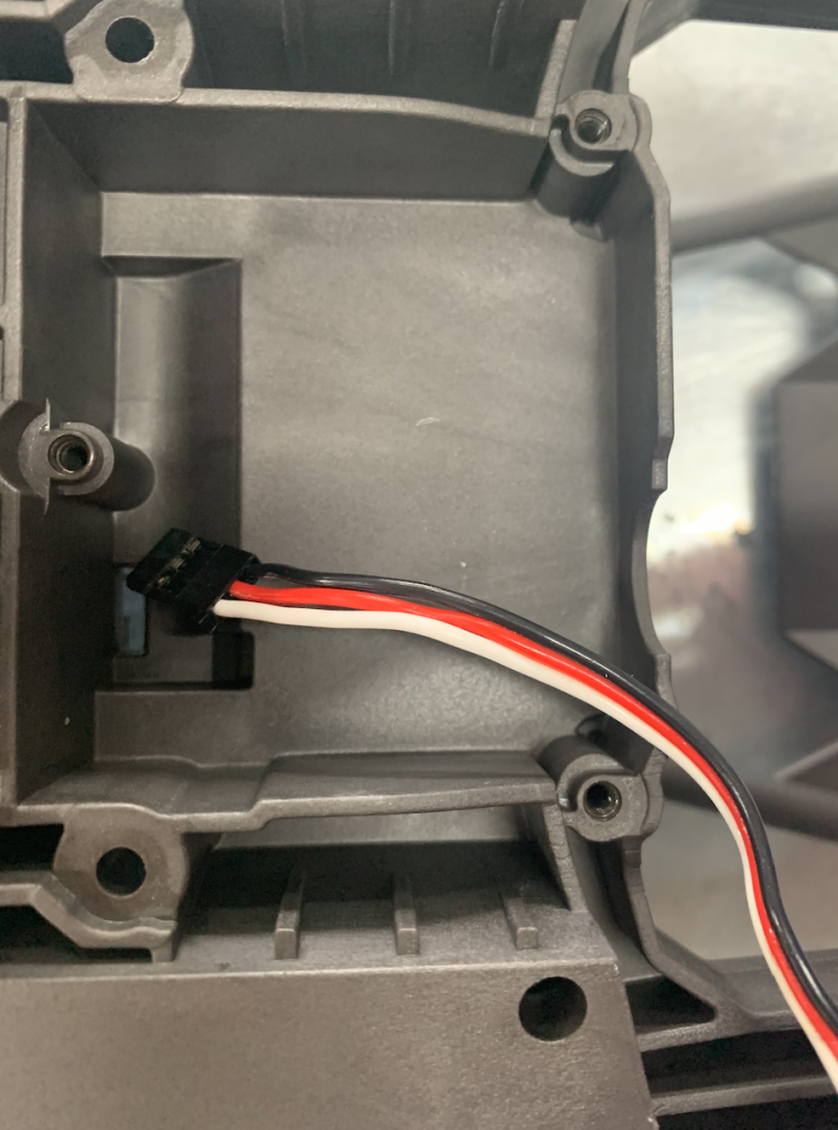
Take 3 screws out en remove it carefully, especially the cable. It has to Coe through the little square hole.

Put it aside, we don’t need it anymore.

Take the new servo, push the cable through the little square hole and put it in the place of the old one.
We don’t use the spring and the steering linkage.
Put the connector with the steering linkage back on the steering servo.
In the video they put the power back on first via the receiver. We don’t do this as the receiver is gone.
So this is tricky.
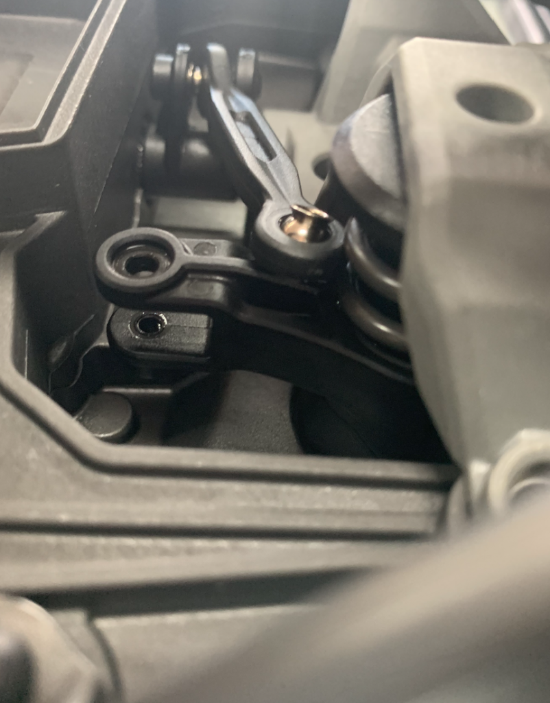
You have to ensure that the steering servo is in the middle.
So put the connector on and turn it as far as possible, don’t force, to the right.
The connector should be horizontal. Otherwise take it off and put it back so it is horizontal. Check this by turning it as fas as possible to the left, again it should be horizontal.
Put it back to the middle position.
Later on we will connect the steering rod.
Let’s move on.
Taking the ESC out
Turn the chassis back again.
You can have a look at this video. In the video it looks more complex because of the connection with the receiver. In our case this is already taken out.
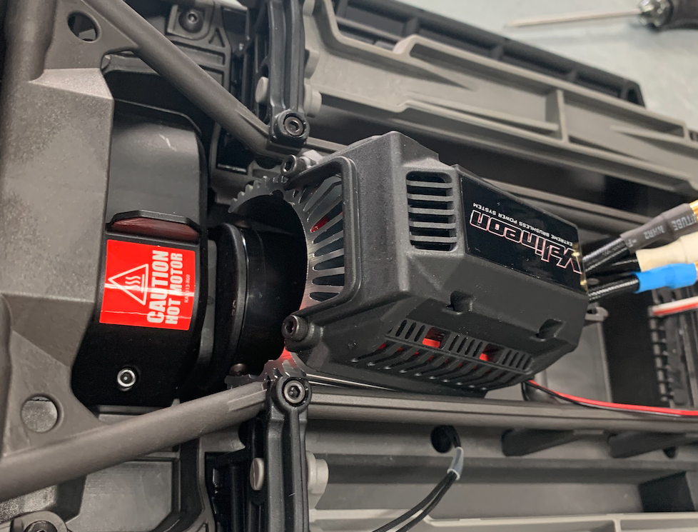
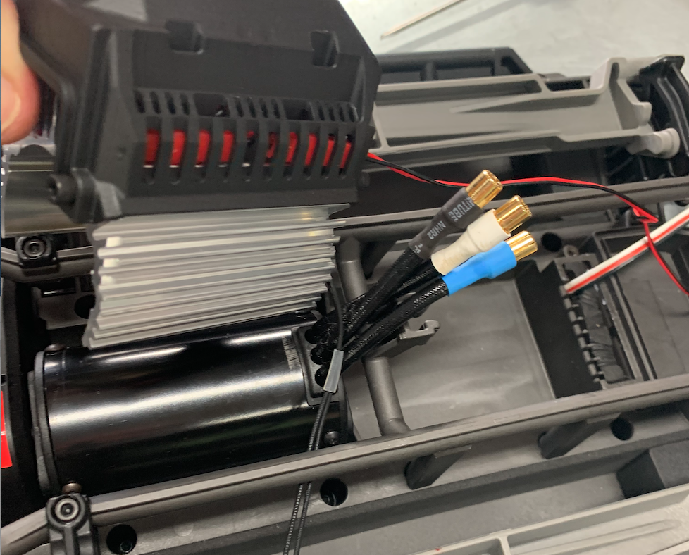
Pull the wires between the motor and the ESC
I don’t remember anymore if and how may screws I took out and I didn’t take the ventilator cover off, but it ended up with taking the ESC out.
I took off the cooler of the main engine.
We don’t need this because the robot drives very slowly. Not 80 km/hour but just 6km/hour.
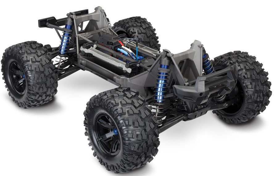
With the receiver, cooler and the ESC out, the vehicle looks a lot simpler.
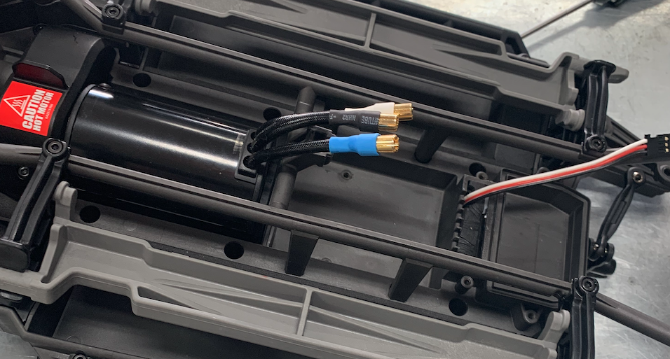
Change the Pinion
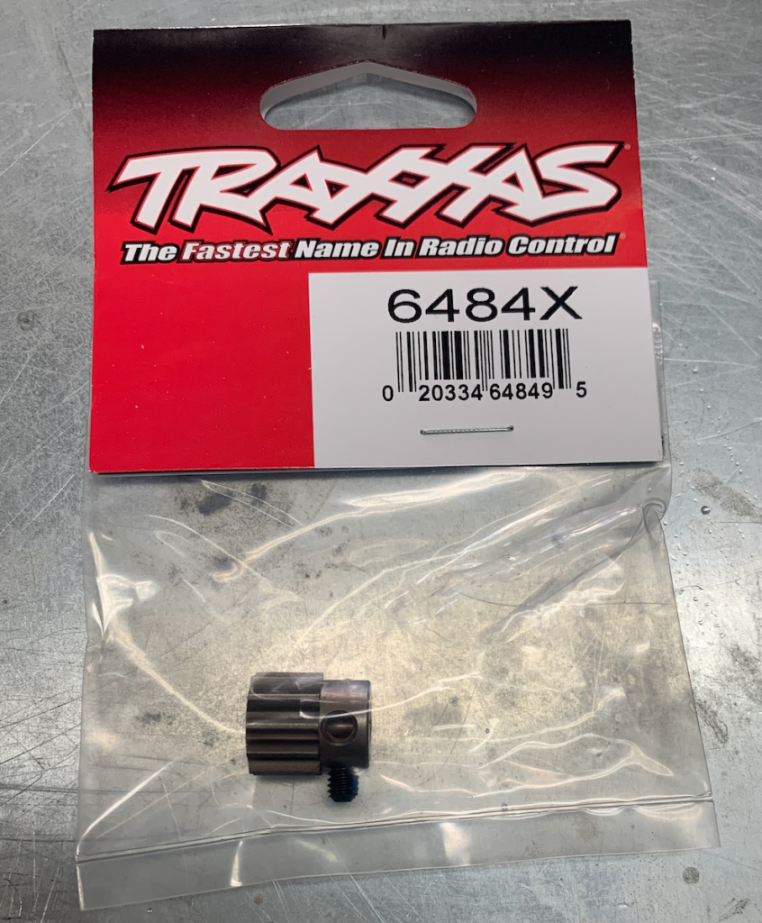
Now we leave the ESC for a while and work on the pinion.
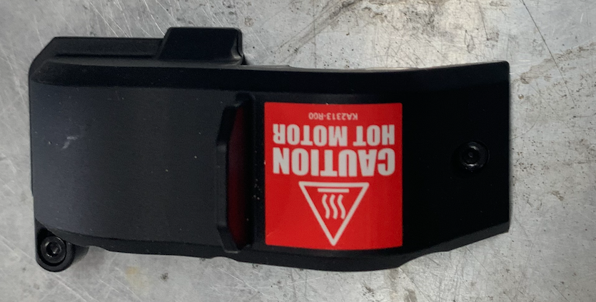
At the back-end of the motor there is a cover.
Take it off.

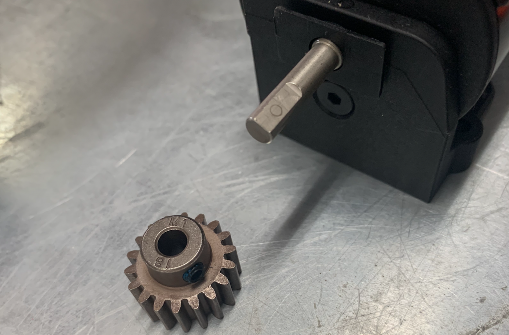
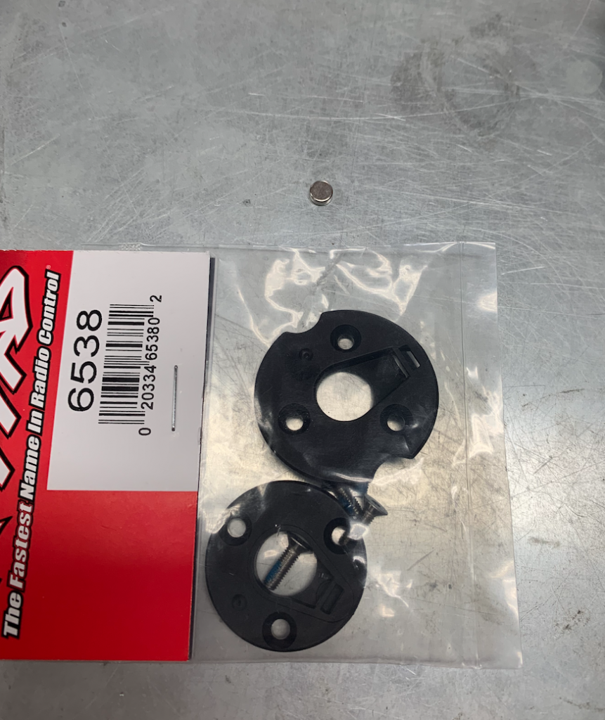
Unpack the pinion, don’t lose the small screw.
Take the screws out and remove the motor.
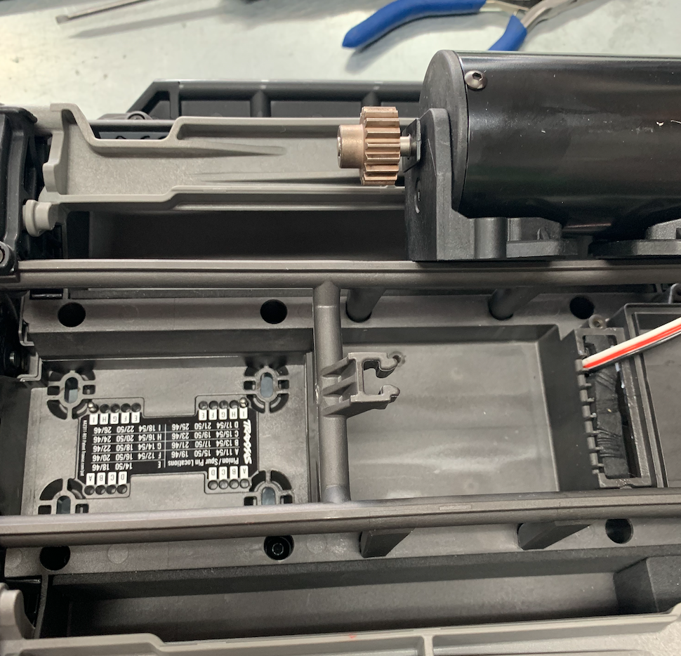
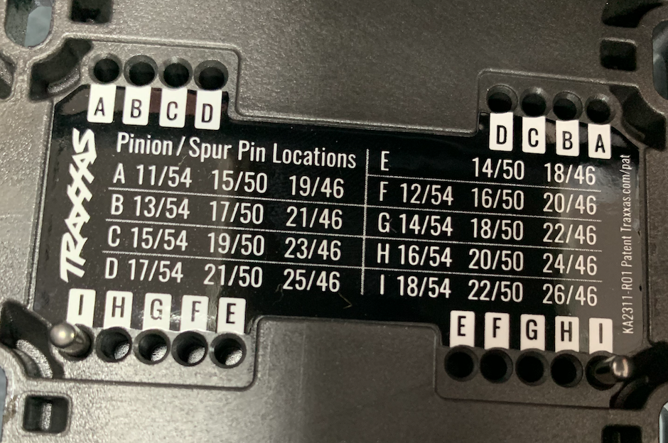
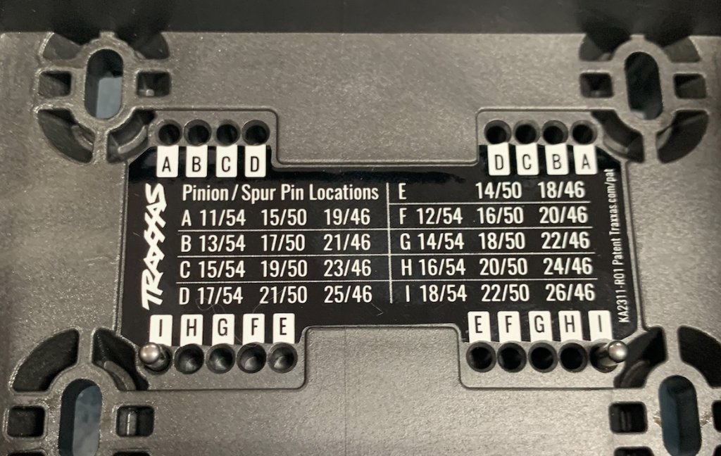
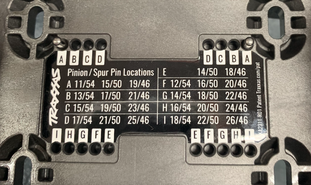
Pay attention to the pin setting. These settings have to be changed later on.
Because the pinion is smaller, the motor has to be moved a little closer to the big sprocket. The original setting is I, it has to go to A.
Don’t lose the pins, take them out carefully.
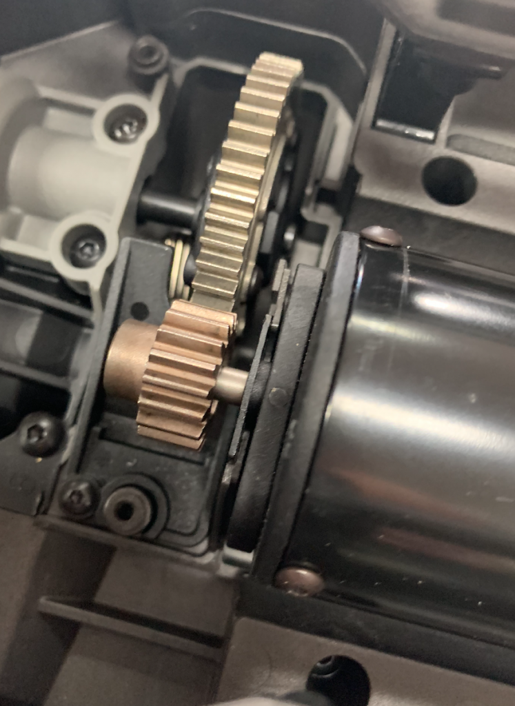
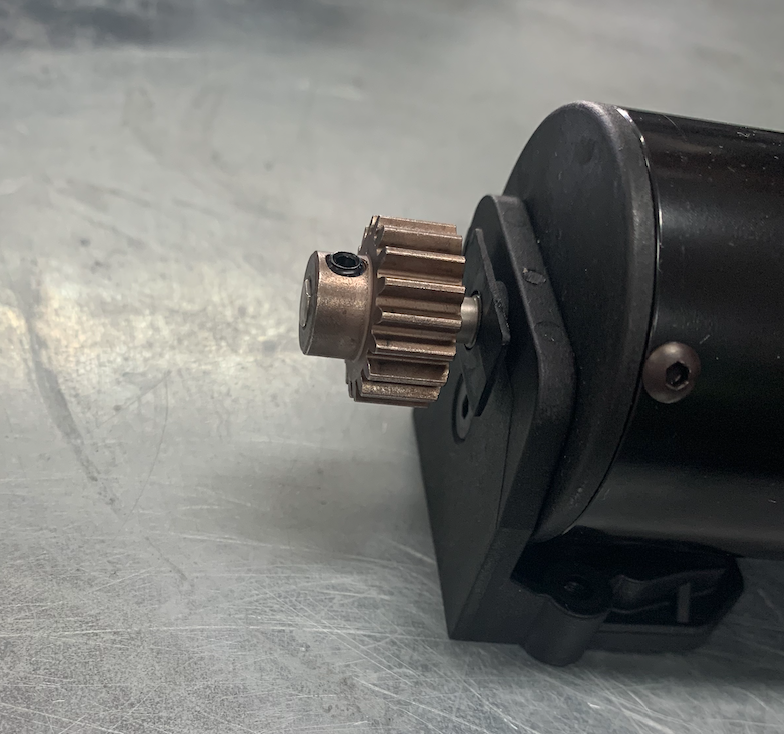
Have a look at the pinion on the motor.
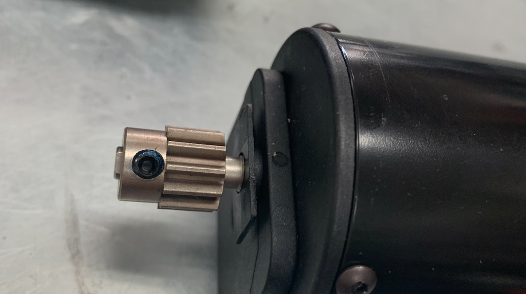
The new pinion should have the same position.
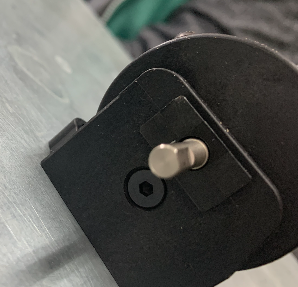
The axis has a flat end to put the pinion screw on.
Take the new pinion, put some Loctite on the screw.
Screw the pinion onto the axis.
We leave this for a while and move on to the tricky part.
The magnet
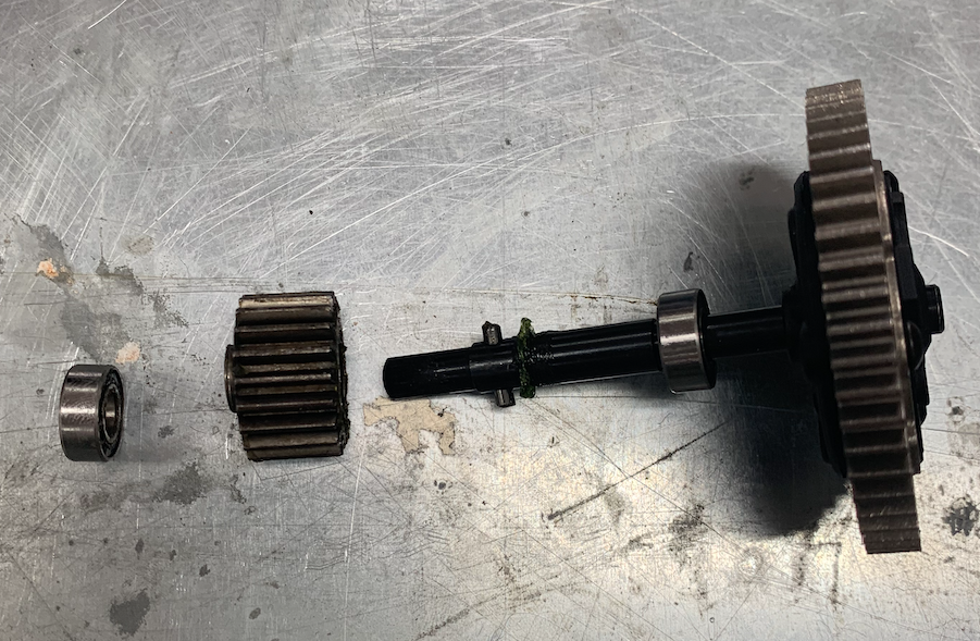
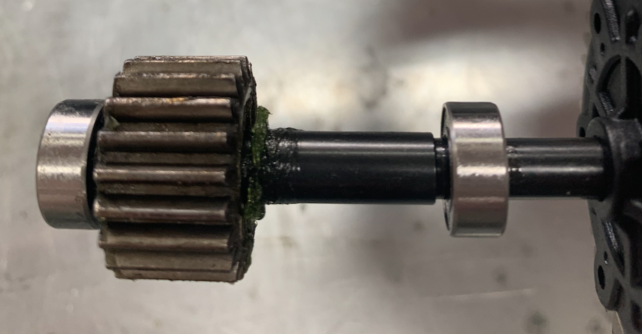
To get some information about the speed we need to get information about the rotations per minute of the motor. Therefor we put a little magnet in the gearbox on a sprocket. This magnet is standard but not for the x-Maxx, so there is no documentation about this part.
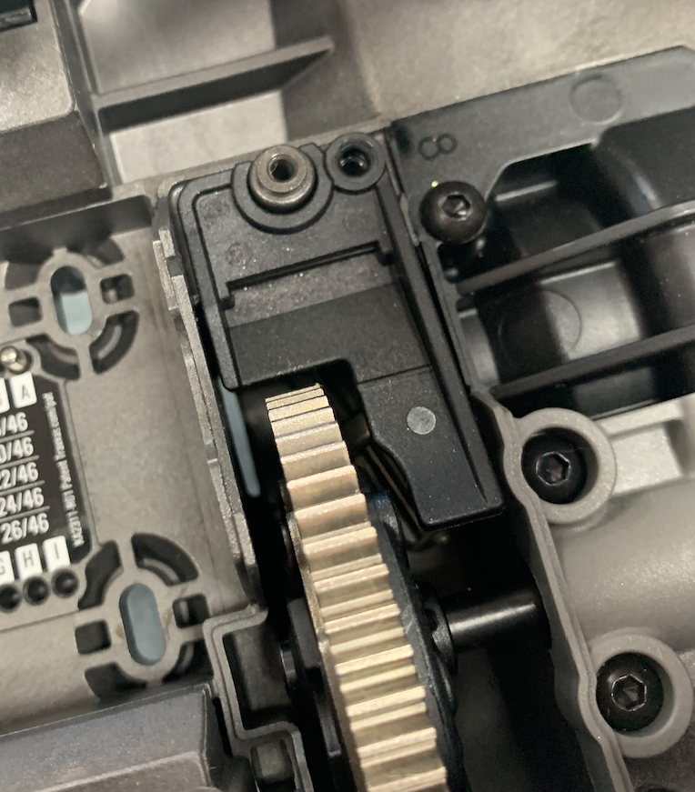
I did this after I put back the motor but I think this wasn’t a good idea. It is more handy to do this before the motor is back in place. So the picture does not show the recommended way to handle this.
Take off the black and grey gearbox covers.

I hope you can take the gears out now.
Don’t let them fall apart. Otherwise put them back together and pay attention to the pins.
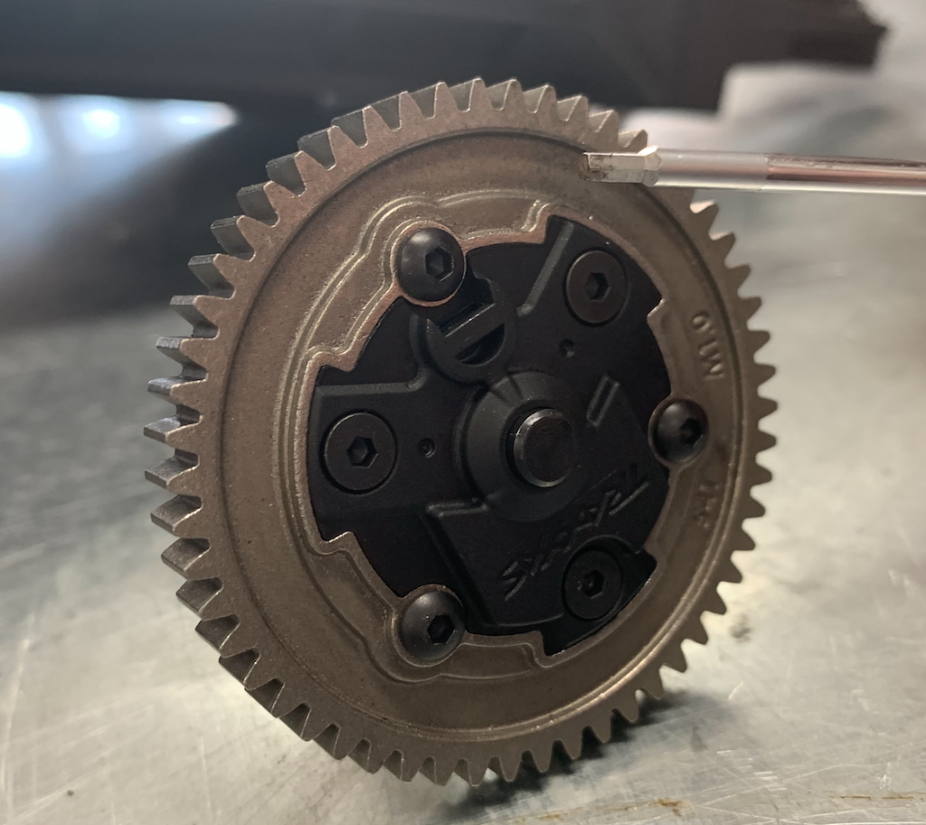
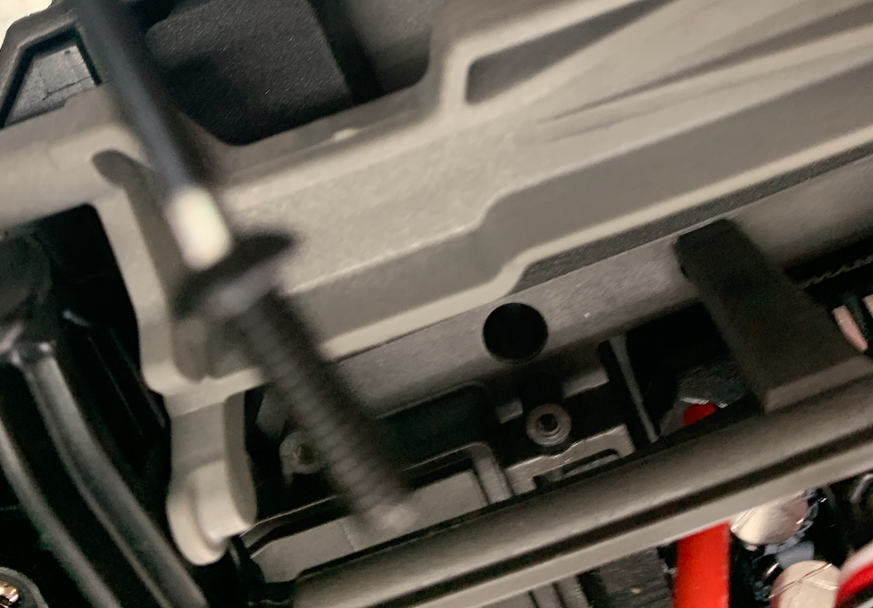
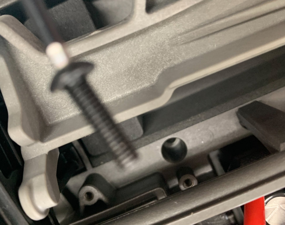
The magnet must be located in the small hole behind the little bar.
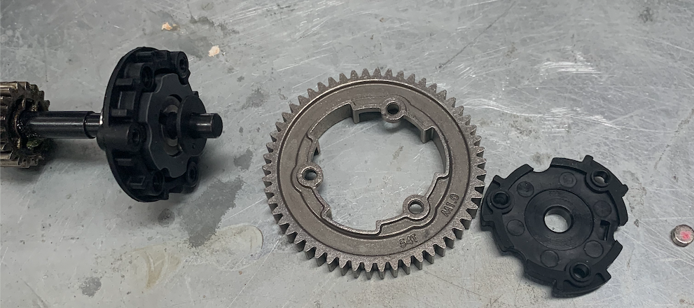
You can take the whole thing apart.

And use pliers to push the magnet in.
I hope to find another way.
Maybe just release a few of the screws a bit and then use the pliers.
Anyway if its in you have to put the whole thing back together and plan it back.
And put the covers on.
Then its time to put the motor back.
Put back motor
Remember the pins.
They were in I and have to go to A.
Then replace the motor and put the screws back.
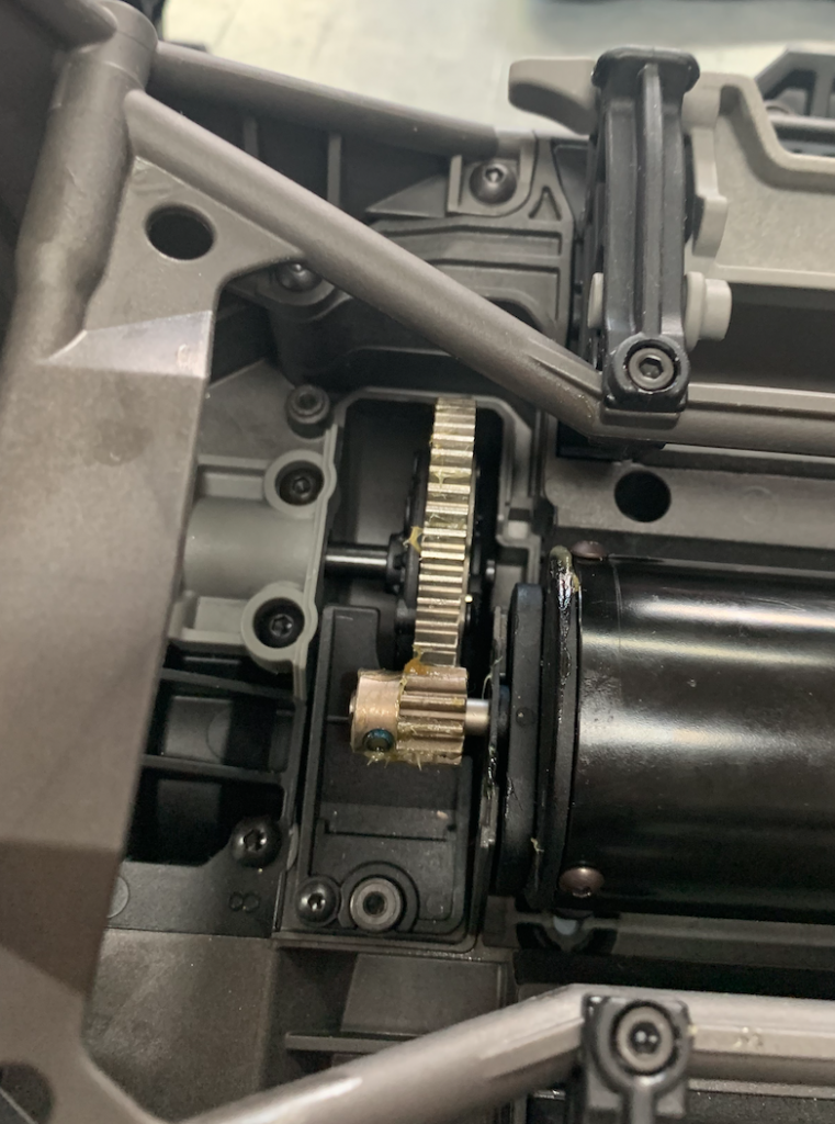
Over to the next step.
The sensor
The sensor also is not standard and not available as a option.
So we have to improvise.
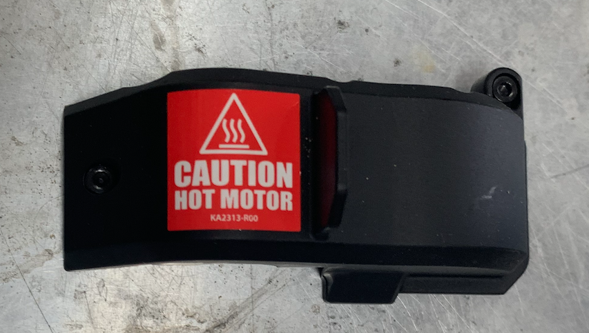
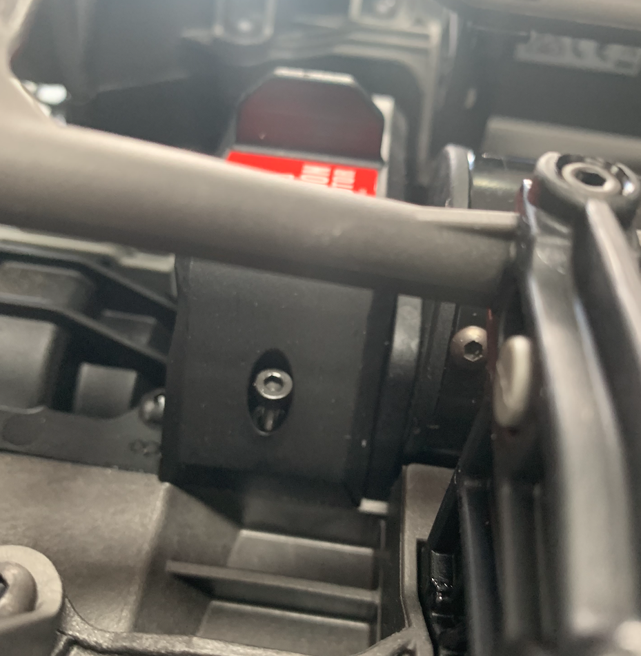
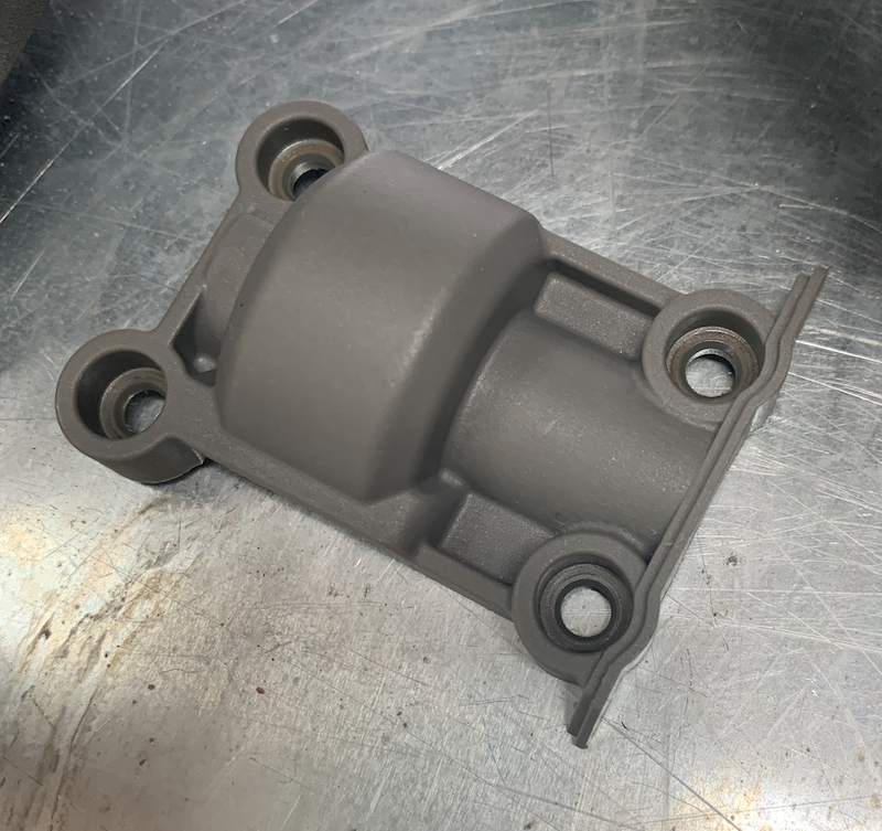
Remember this cover
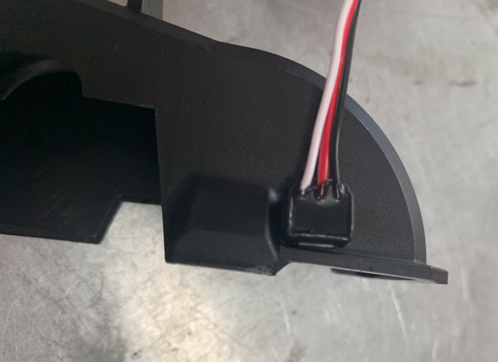
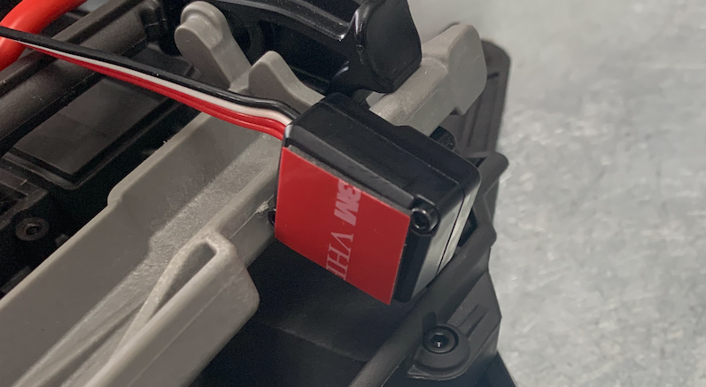
The sensor should be stuck onto this cover.
Please note!! The side where the wire is attached to the sensor should face away from the cover.

Get a lot of paper.
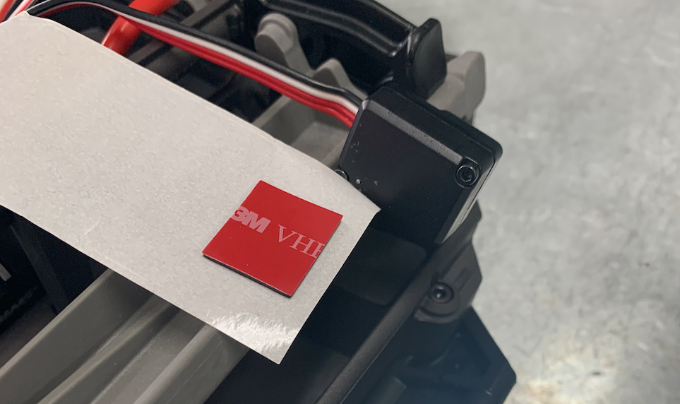
To put the sensor in place we need this nasty glue or something like it.
Don’t get it on to your fingers.
Also get the duct tape to keep the sensor in place after glueing it.
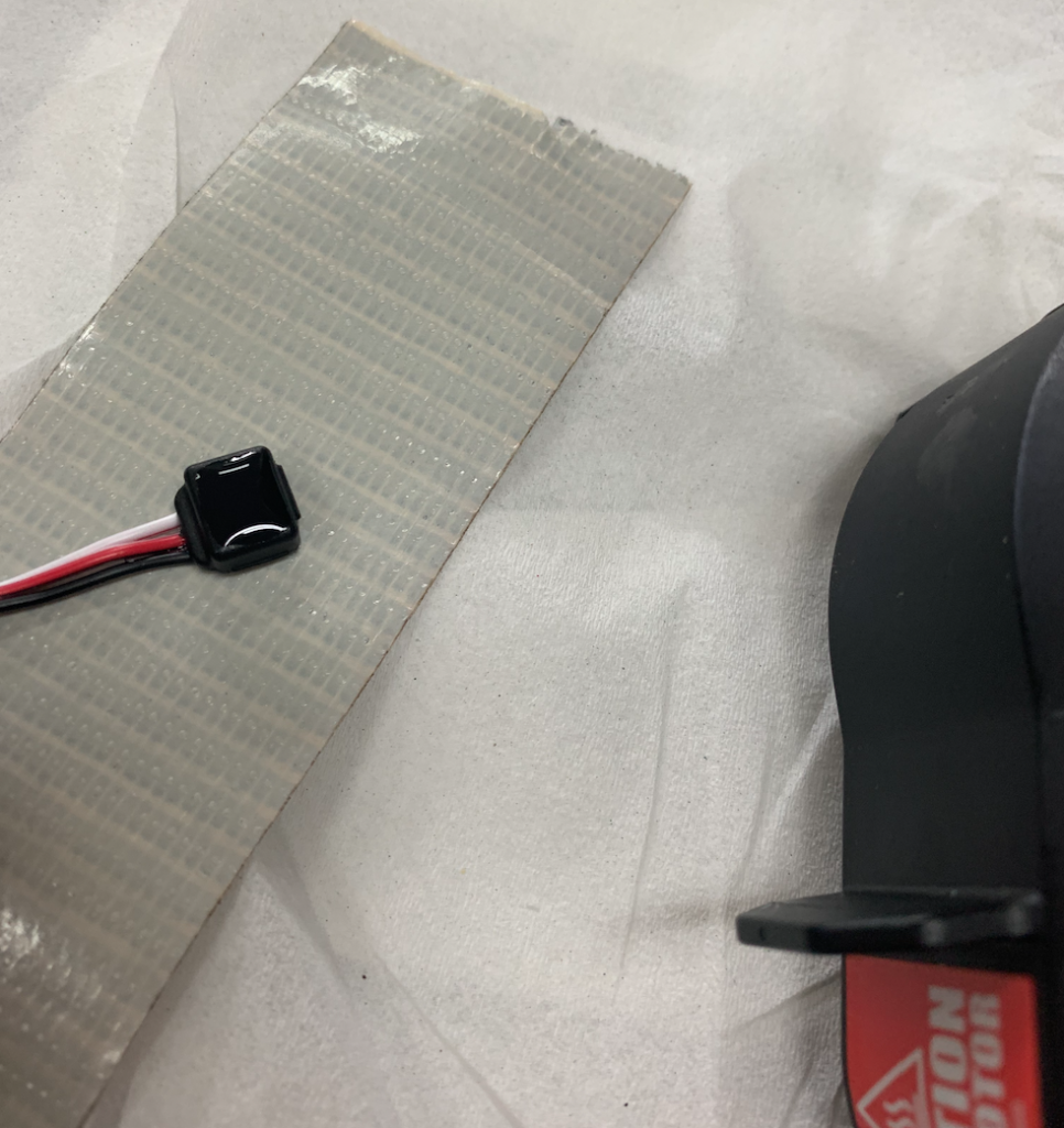
This is what I did.
I attached the sensor with the wire side to the duct tape.
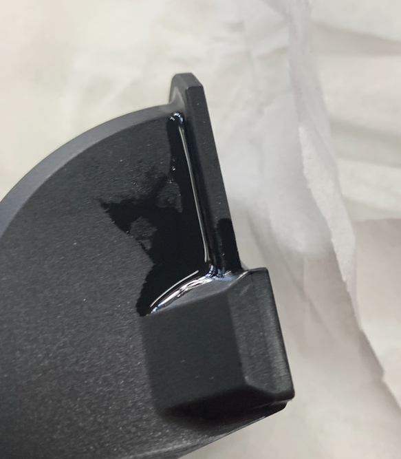
Then I put the glue on the cover
I pressed the sensor on the glue and stuck the tape to the cover so the sensor was fixated.
While waiting we can carry on with the ESC
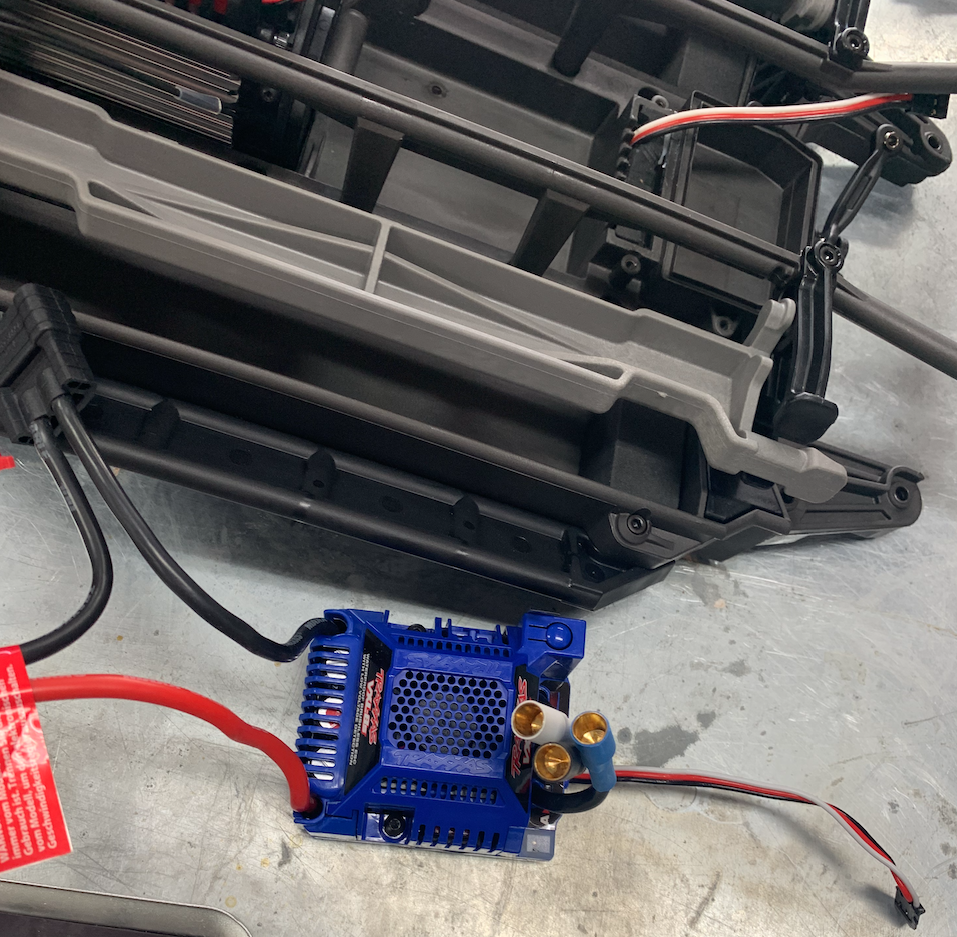
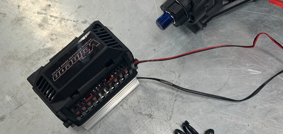
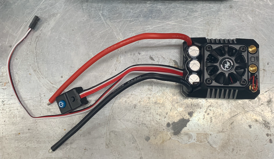
Placing the new ESC
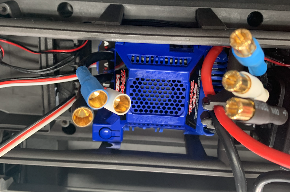
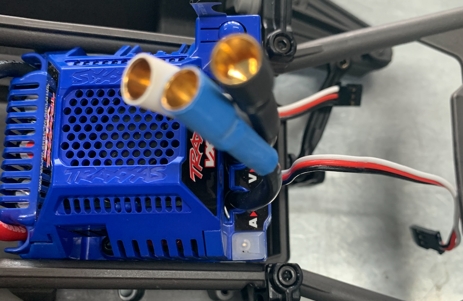
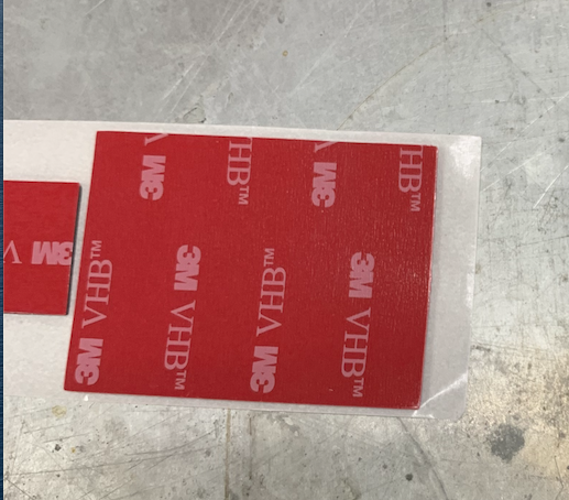
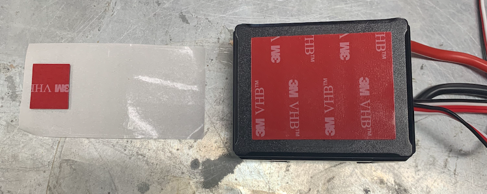
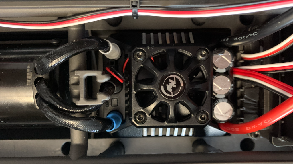
Unpack the new ESC and put the double sided adhesive tape on the bottom.
Put the ESC into the chassis in the place of the old ESC.
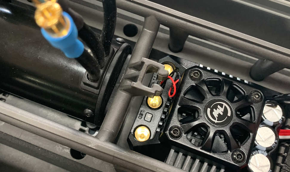
Gold connectors at the motor side.
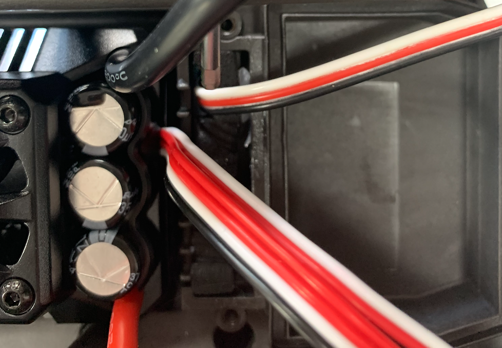
Put is as far as possible to the front but leave 1-1,5 mm free for the cables at the front. So there is a lot more space at the back than at the front.
Put the motor cables in place.
Stick the other tape to the on/of button
Oke, lets put it together.
Connect front to back
Put the chassis upside-down.
Slide the from into the back.
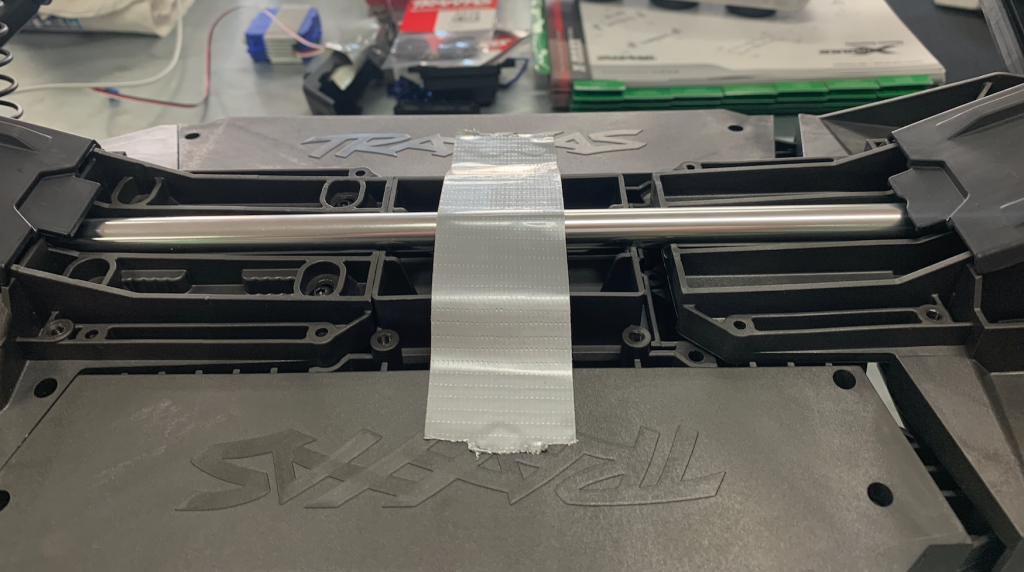
There might some resistance from the main axis. The sprocket has to fit. Try to turn the axes of both front wheels.
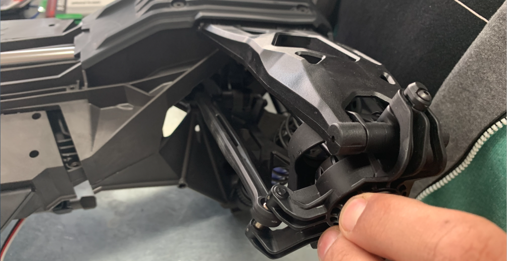
And press until it fits.
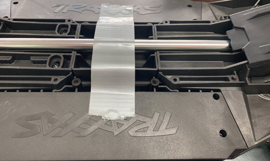
Put the screws back.
Connect the steering rod.
I think the only thing left is replacing the cover with the sensor.
This might take some time, the sensor might be a bit to wide. Then you need to push it in place.
Power connector
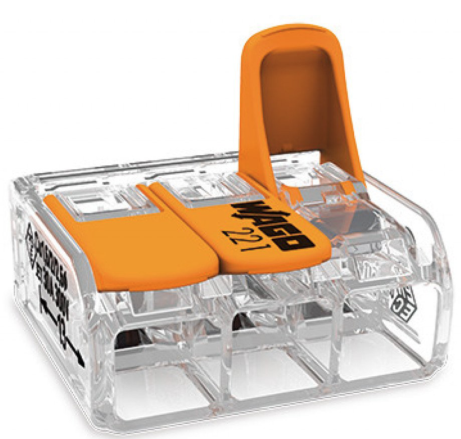
The connector on the ESC must be connected to the power supply. To do this and avoid soldering, a wired XT90 male can be coupled to the wires on the ESC using two Wago 221-612 connectors.

Oke, that’s it. As I said, if you do this for the fist time, it can take several days.
0.1-200408 First version

