>> Introduction / Content
0.1 2003270041
>> Introduction / Content
To help you replace these parts several videos are available. These videos make it all look quite simple. But it took us much longer and we ran into several issues that are not shown on these videos. If you do this for the fist time, it can take several days:
The above videos deal with just one subject. In our makeover we have to combine them.
And also, we don’t put back the receiver and the cooler.
Lets go!
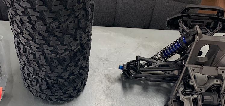
We took off the wheels.

We start with the steering servo.
From the contents of the package we don’t use the spring and the steering linkage.
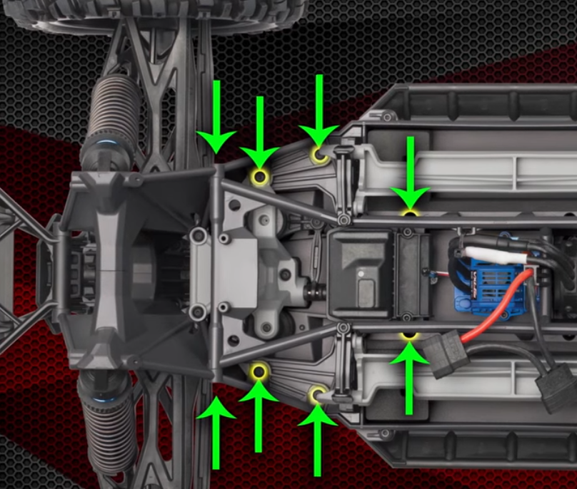
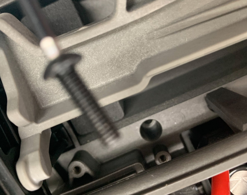
Remove the screw etc.
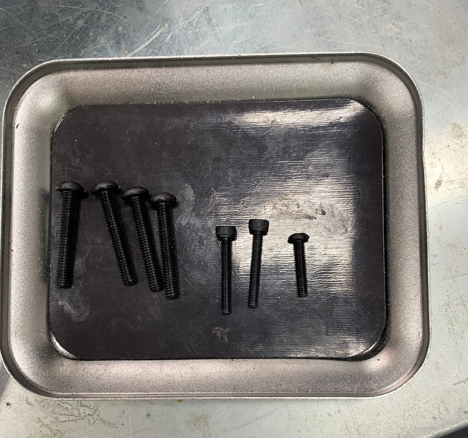
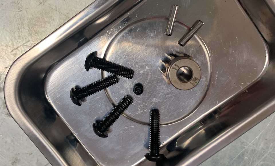
Collect the screws in a little tray
Follow the steering servo video until second 0:51.
Don’t pull the front off.
First go to second 0:55 and remove the center skid plate
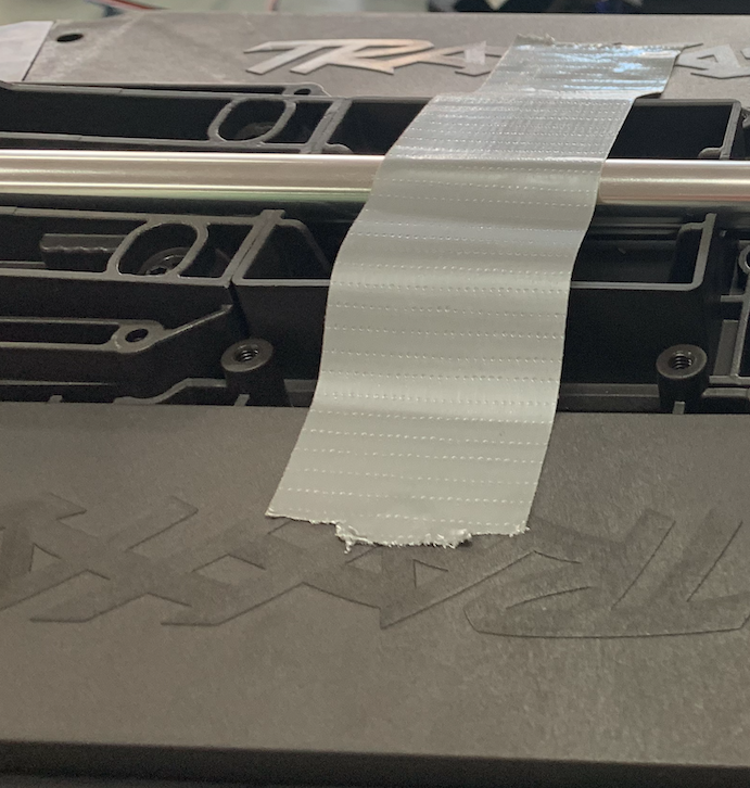
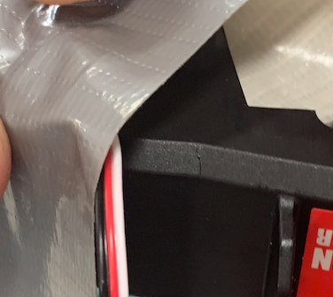
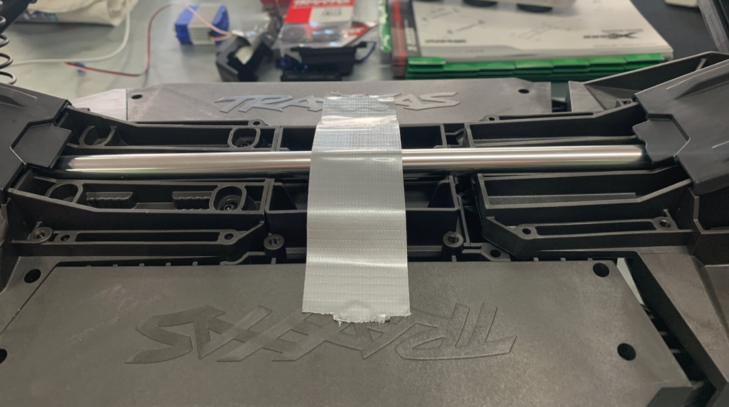
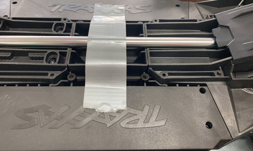
Stick the main axle with duct-tape to the back .
If the main axis is moving to much and the chassis is turned, the connector can drop into the gearbox.
If that happens you have to place it back and this wil take another hour.
Let’s hope this doesn’t happen and you won’t recognise these pictures.
After sticking the axis to the chassis we continue with the video from second 0:51.
Follow the video until 1:25.
Then disconnect all wires from the receiver and take the antenne and the receiver out.
You can store these, we won’t put these back.

To disconnect the antenne, take out the little screw.

Don’t lose it.

Take the antenne carefully off the wire and put it aside.
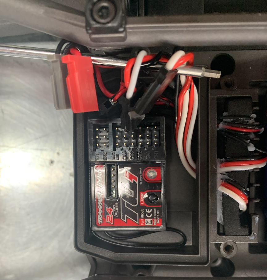
Pull all wires from the receiver.
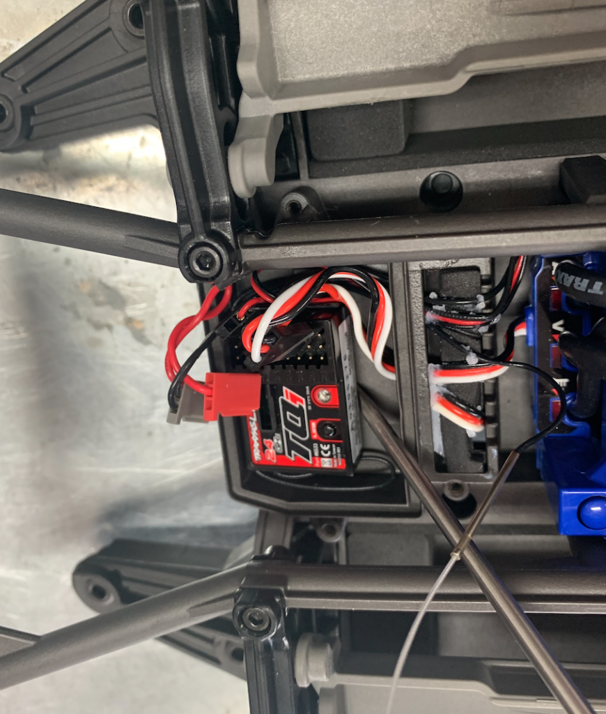
Take the receiver out.
If necessary, don’t hesitate to use the screwdriver.
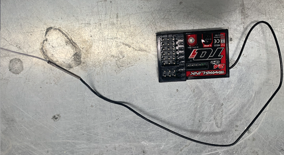
And put it aside.
The place where the receiver was is empty and, although we put the cover back, wil stay empty.

Turn the chassis upside-down again.
Let’s change the steering servo.
Follow the instructions in the video from 1:28 to 1:48.
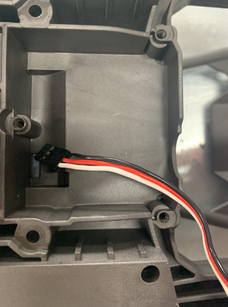
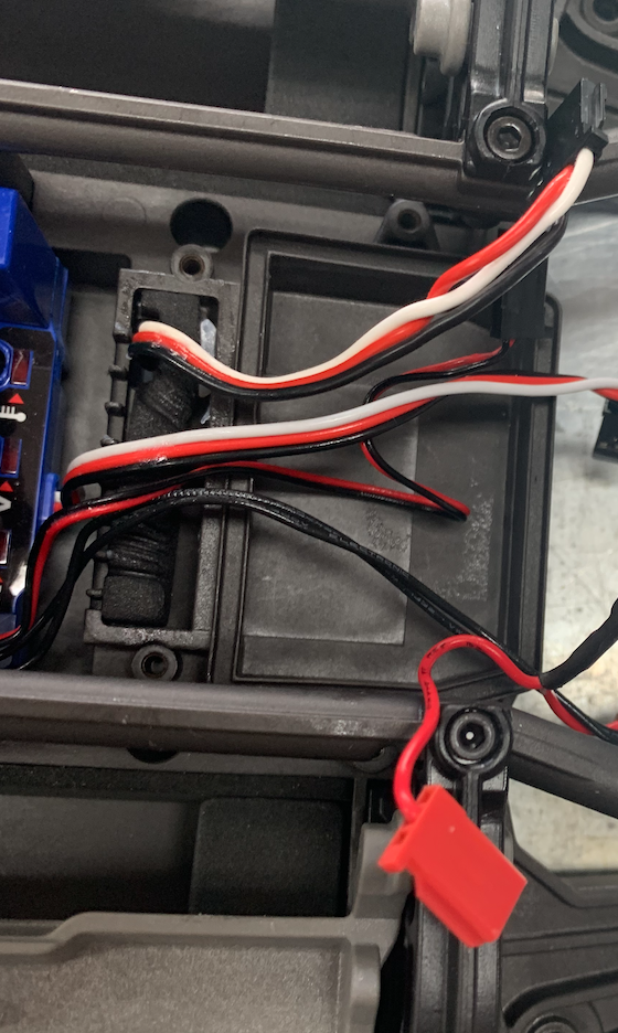
Take 3 screws out en remove it carefully, especially the cable. It has to Coe through the little square hole.

Put it aside, we don’t need it anymore.

Take the new servo, push the cable through the little square hole and put it in the place of the old one.
We don’t use the spring and the steering linkage.
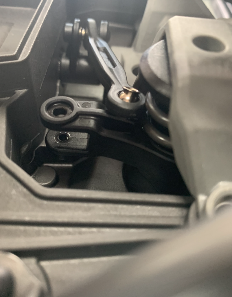
Put the connector with the steering linkage back on the steering servo.
In the video they put the power back on first via the receiver. We don’t do this as the receiver is gone.
So this is tricky.
You have to ensure that the steering servo is in the middle.
So put the connector on and turn it as far as possible, don’t force, to the right.
The connector should be horizontal. Otherwise take it off and put it back so it is horizontal. Check this by turning it as fas as possible to the left, again it should be horizontal.
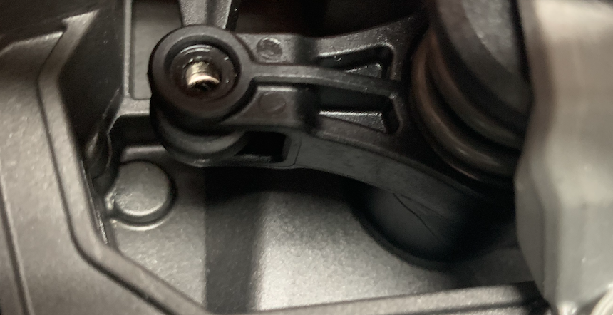
Put it back to the middle position.
Later on we will connect the steering rod.
Let’s move on.
Turn the chassis back again.
You can have a look at this video. In the video it looks more complex because of the connection with the receiver. In our case this is already taken out.
Pull the wires between the motor and the ESC

I don’t remember anymore if and how may screws I took out and I didn’t take the ventilator cover off, but it ended up with taking the ESC out.
I took off the cooler of the main engine.
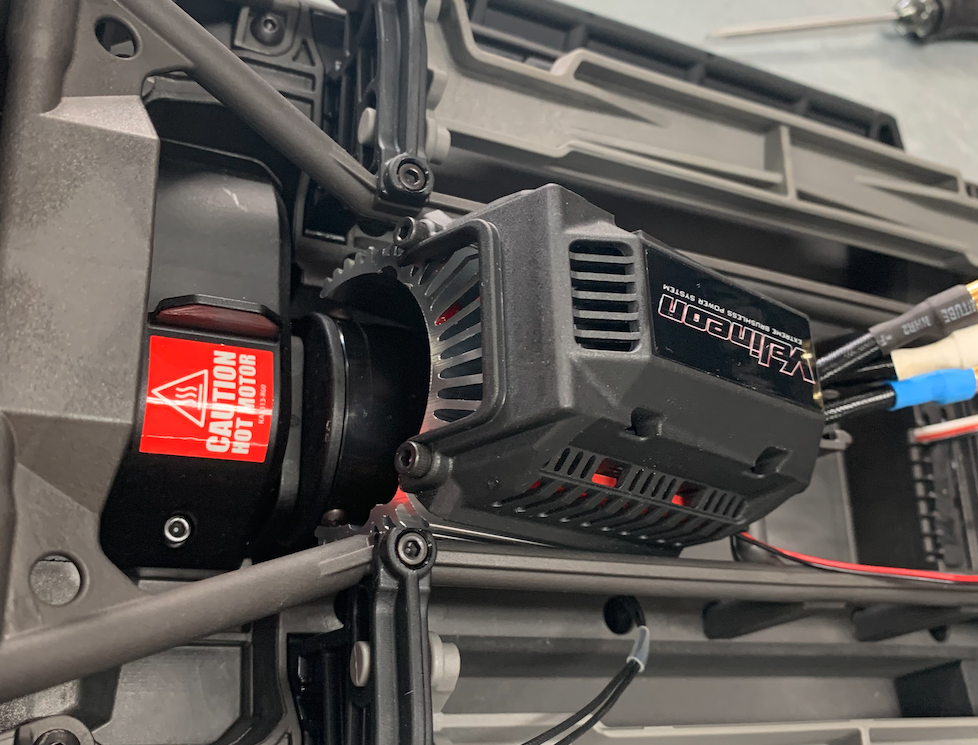
We don’t need this because the robot drives very slowly. Not 80 km/hour but just 6km/hour.
With the receiver, cooler and the ESC out, the vehicle looks a lot simpler.
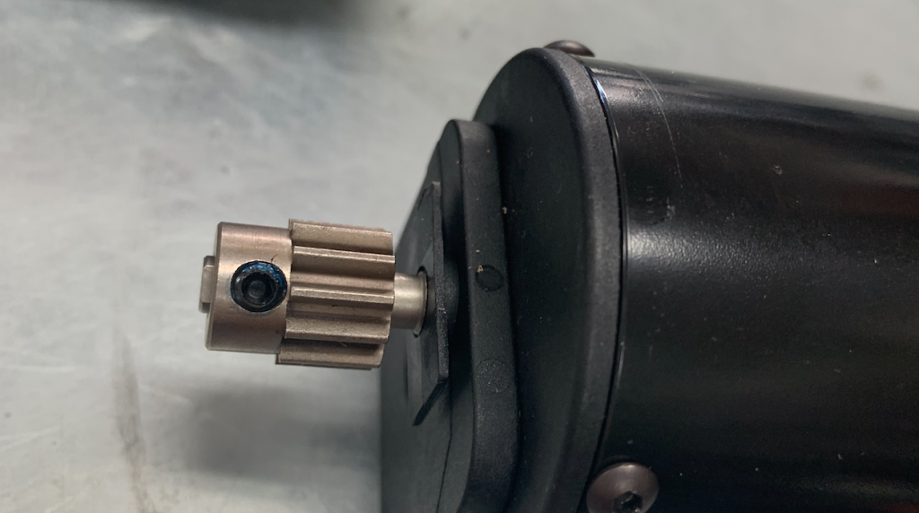
Now we leave the ESC for a while and work on the pinion.
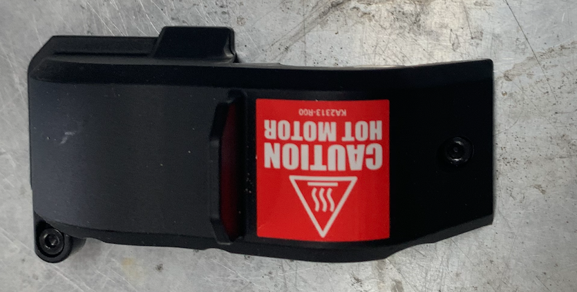
At the back-end of the motor there is a cover.
Take it off.


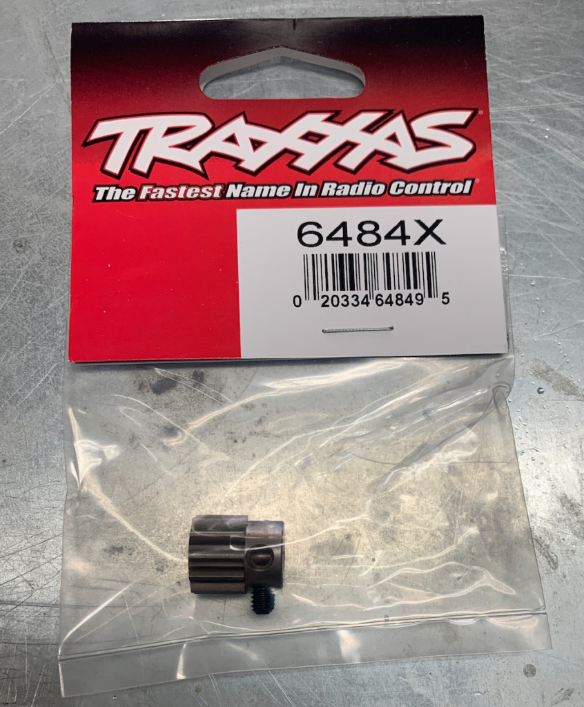
Unpack the pinion, don’t lose the small screw.
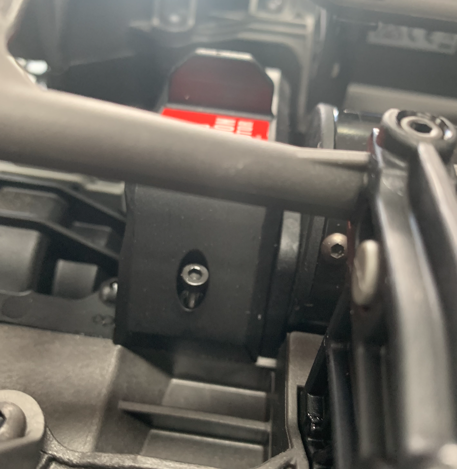
Take the screws out and remove the motor.
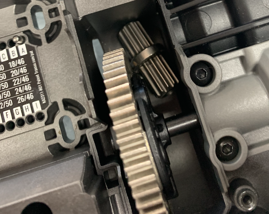
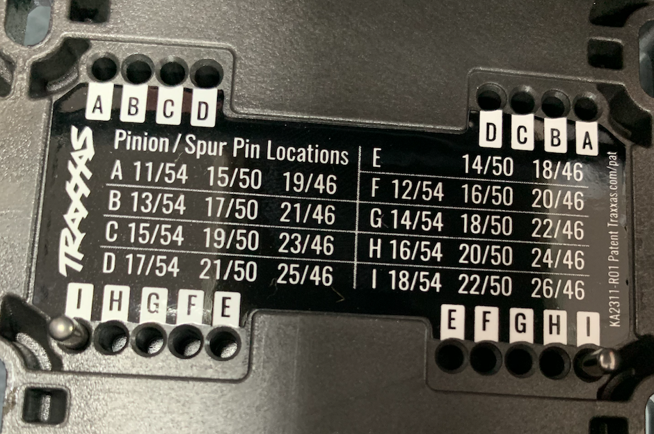
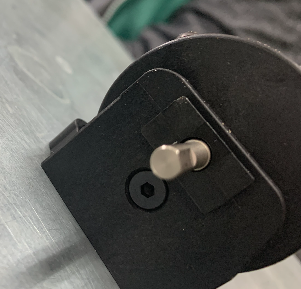
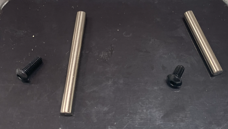
Pay attention to the pin setting. These settings have to be changed later on.
Because the pinion is smaller, the motor has to be moved a little closer to the big sprocket. The original setting is I, it has to go to A.
Don’t lose the pins, take them out carefully.


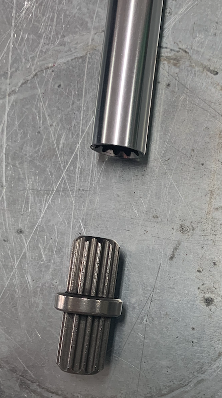
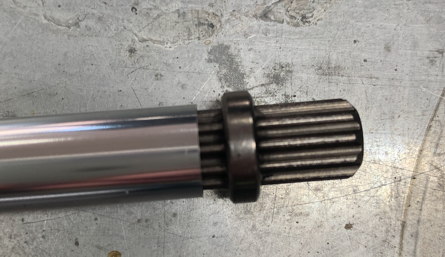
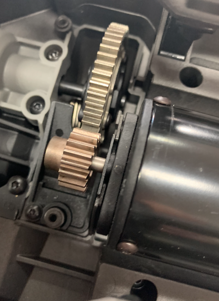
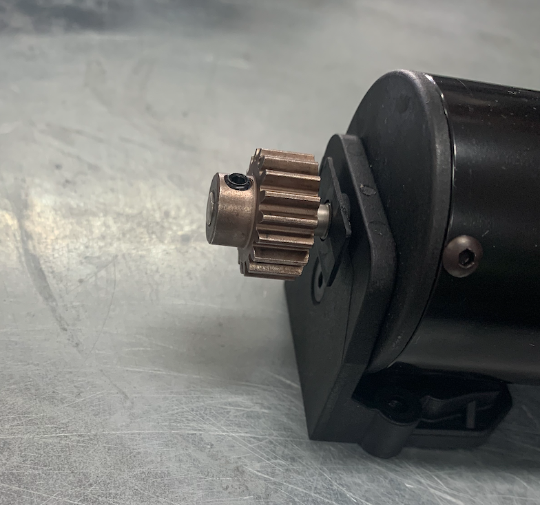
Have a look at the pinion on the motor.
The new pinion should have the same position.
The axis has a flat end to put the pinion screw on.
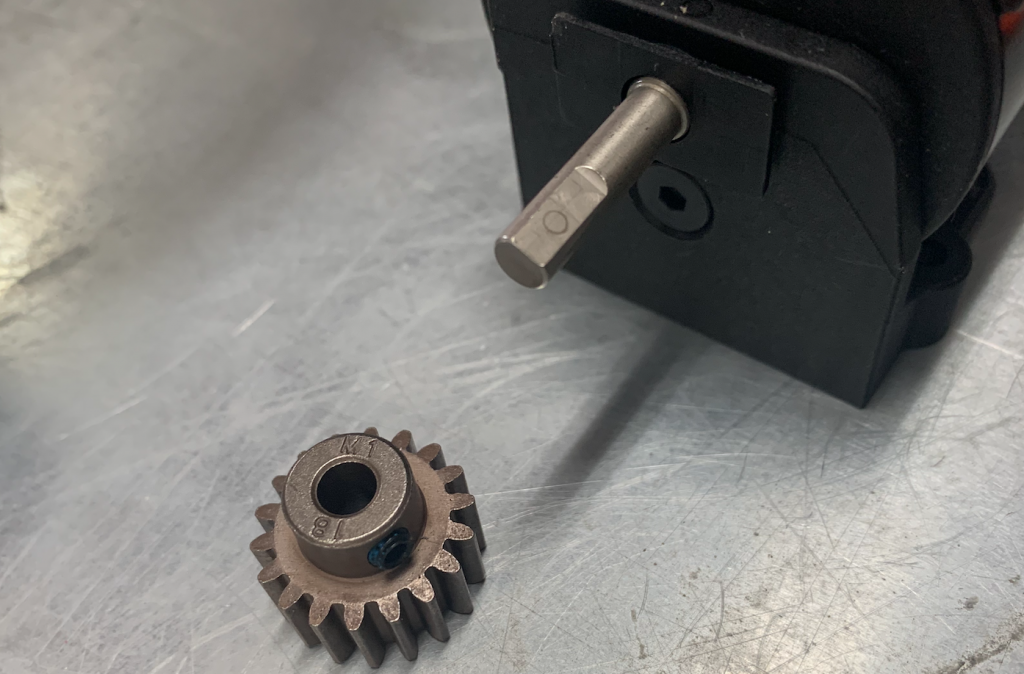
Take the new pinion, put some Loctite on the screw.
Screw the pinion onto the axis.


We leave this for a while and move on to the tricky part.
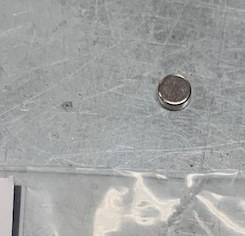
To get some information about the speed we need to get information about the rotations per minute of the motor. Therefor we put a little magnet in the gearbox on a sprocket. This magnet is standard but not for the x-Maxx, so there is no documentation about this part.
I did this after I put back the motor but I think this wasn’t a good idea. It is more handy to do this before the motor is back in place. So the picture does not show the recommended way to handle this.
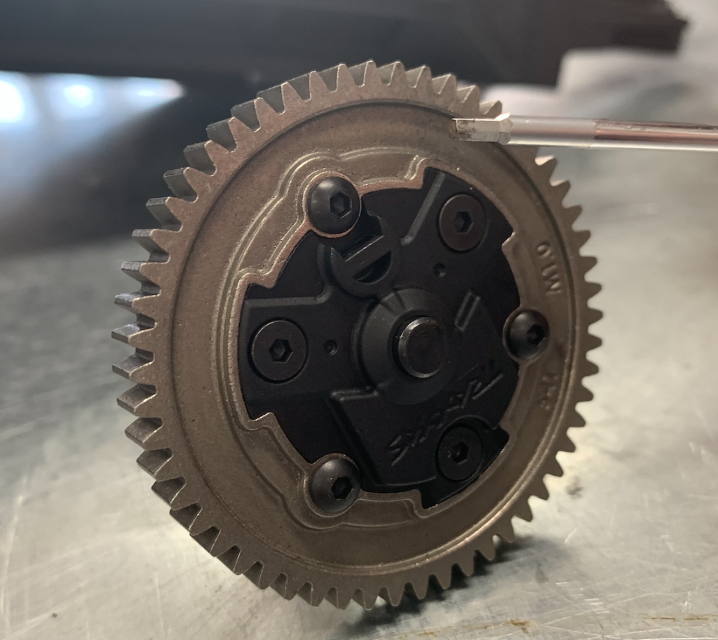
Take off the black and grey gearbox covers.
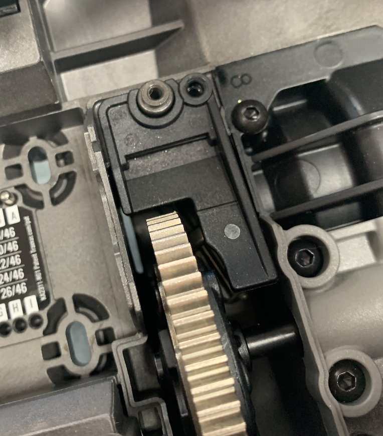


I hope you can take the gears out now.
Don’t let them fall apart. Otherwise put them back together and pay attention to the pins.
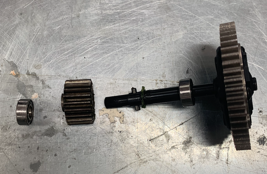
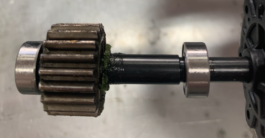
The magnet must be located in the small hole behind the little bar.
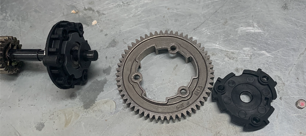
You can take the whole thing apart.

And use pliers to push the magnet in.
I hope to find another way.
Maybe just release a few of the screws a bit and then use the pliers.
Anyway if its in you have to put the whole thing back together and plan it back.
And put the covers on.
Then its time to put the motor back.
Remember the pins.
They were in I and have to go to A.
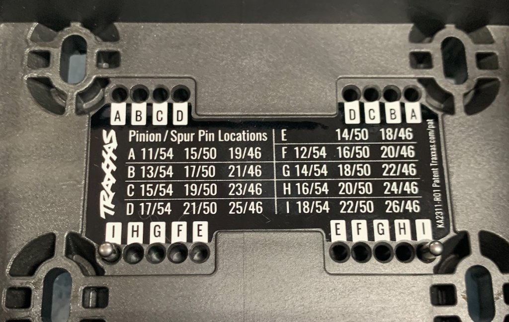
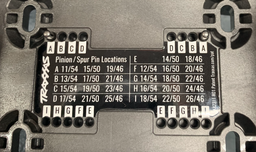
Then replace the motor and put the screws back.
Over to the next step.
The sensor also is not standard and not available as a option.
So we have to improvise.
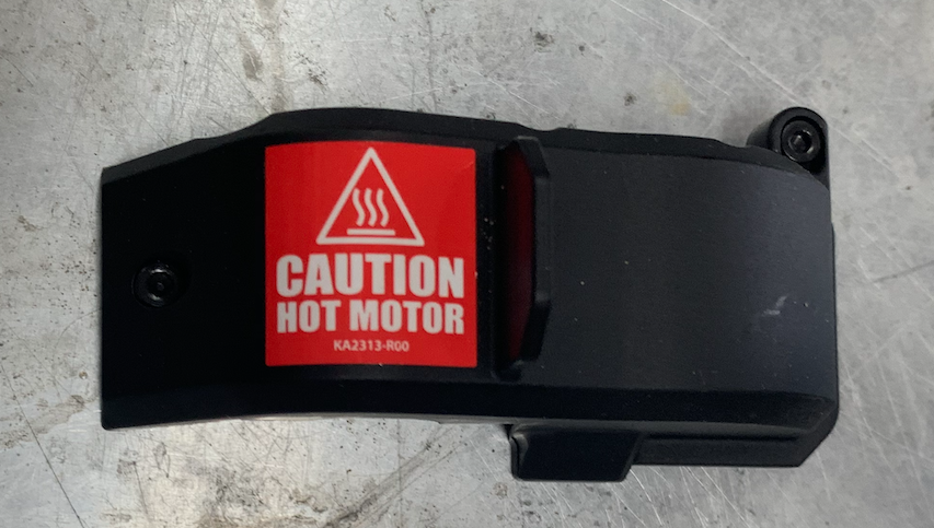
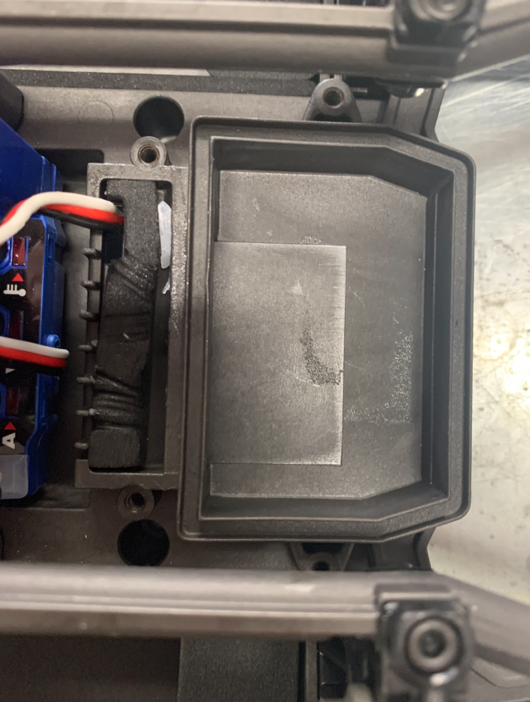
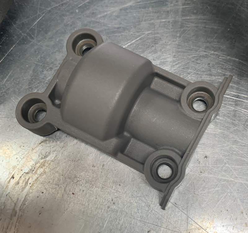
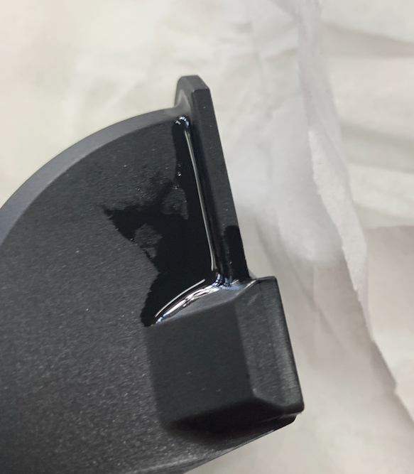
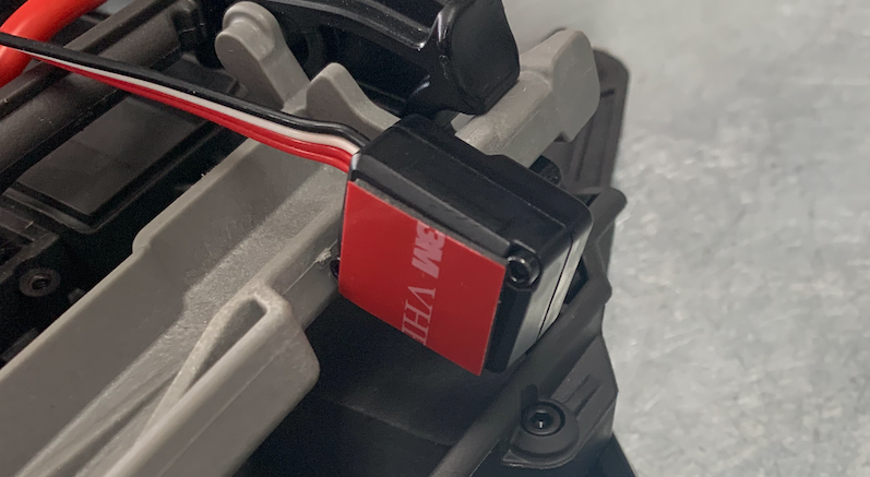
Remember this cover
The sensor should be stuck onto this cover.
Please note!! The side where the wire is attached to the sensor should face away from the cover.

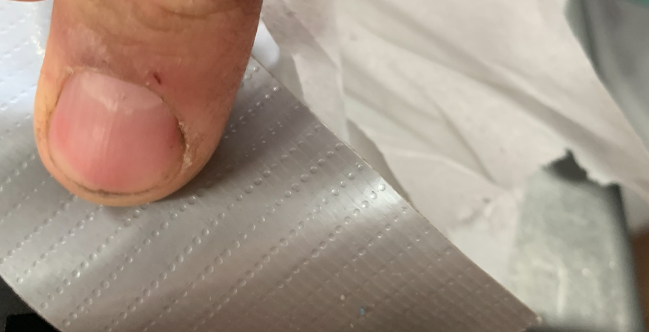
Get a lot of paper.
To put the sensor in place we need this nasty glue or something like it.
Don’t get it on to your fingers.
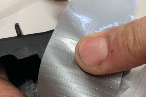
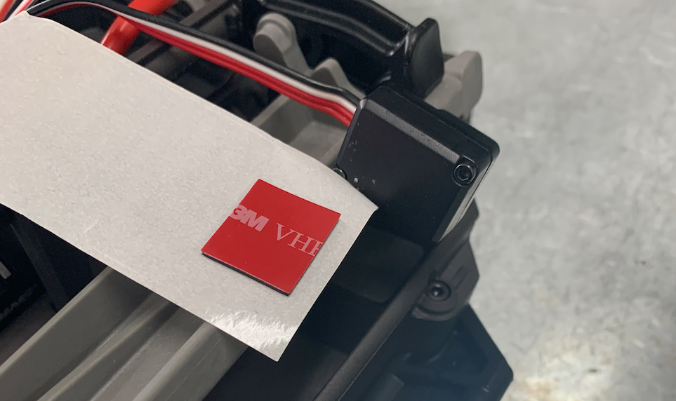
Also get the duct tape to keep the sensor in place after glueing it.
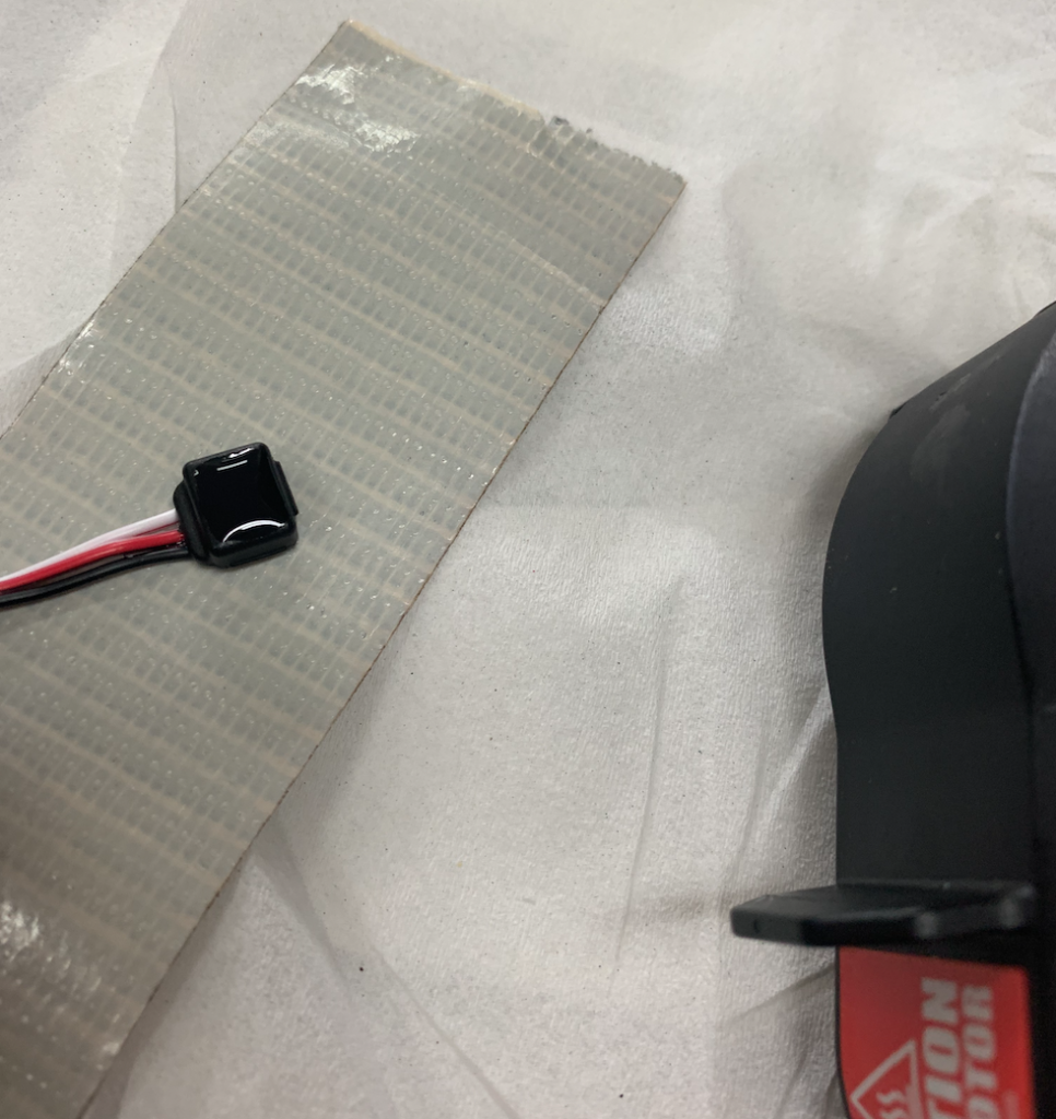
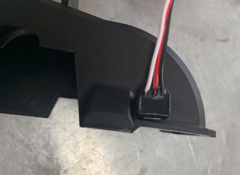
This is what I did.
I attached the sensor with the wire side to the duct tape.
Then I put the glue on the cover
I pressed the sensor on the glue and stuck the tape to the cover so the sensor was fixated.
While waiting we can carry on with the ESC
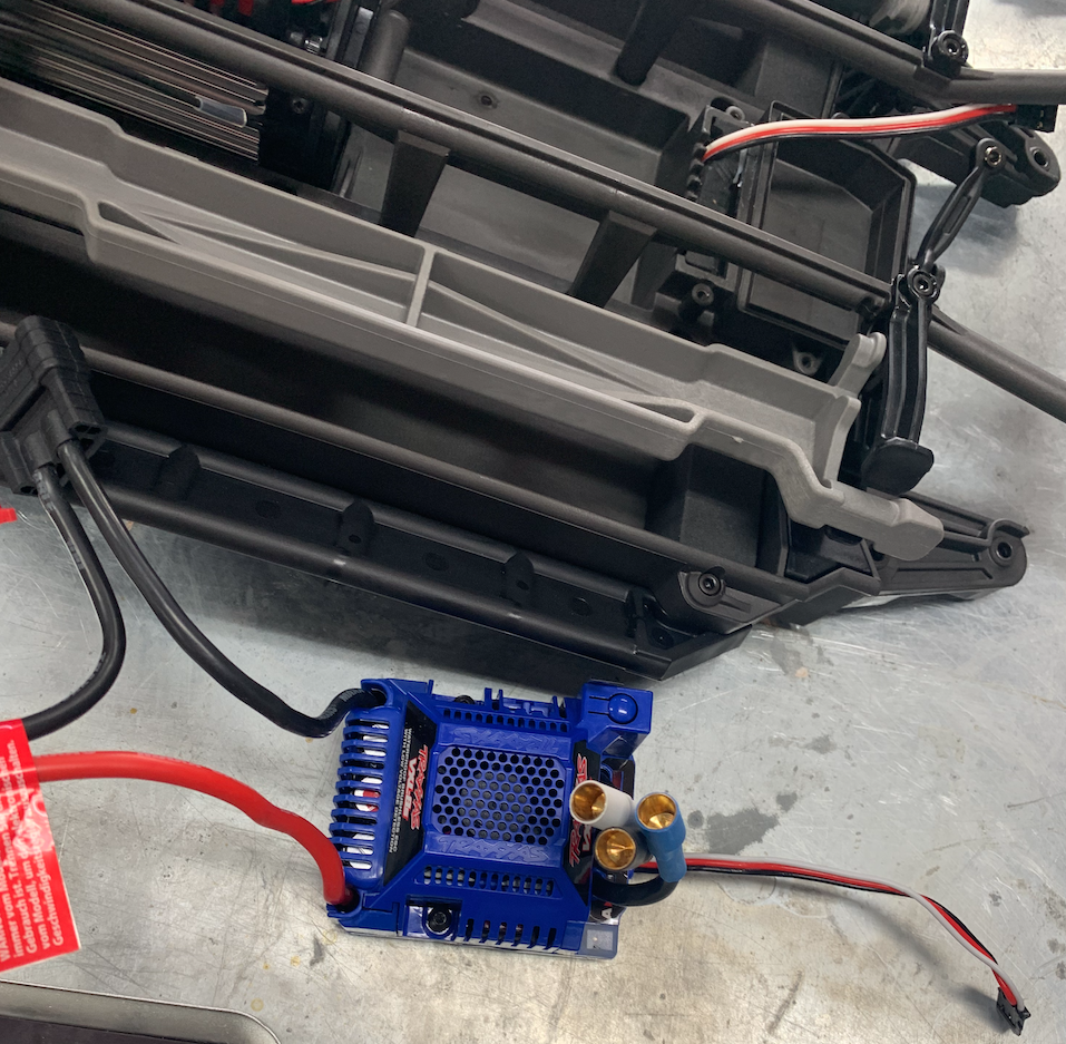
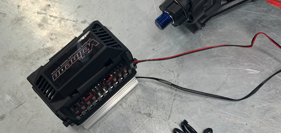
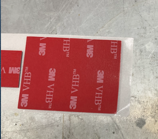
Unpack the new ESC and put the double sided adhesive tape on the bottom.
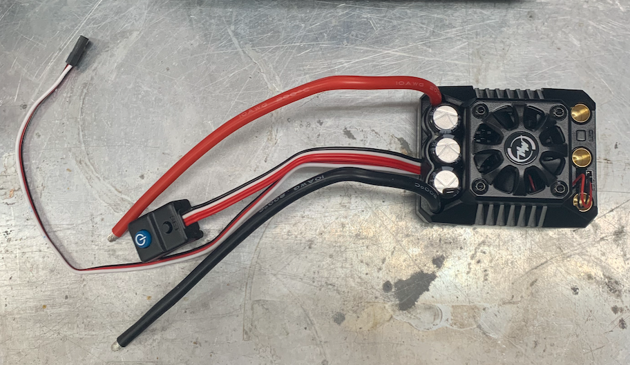
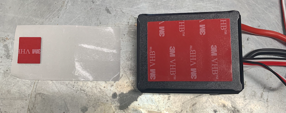
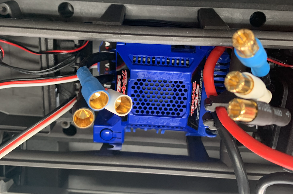
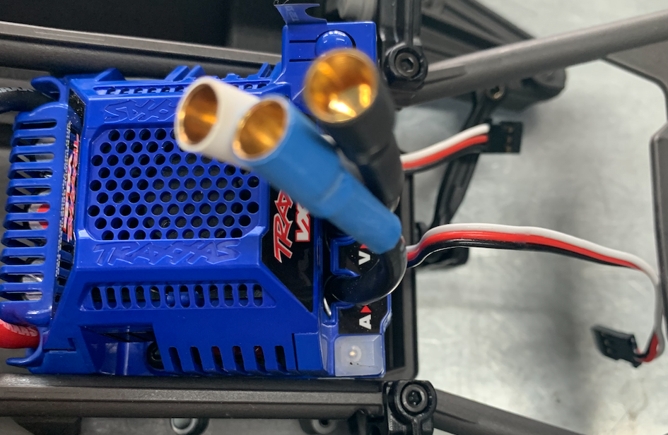
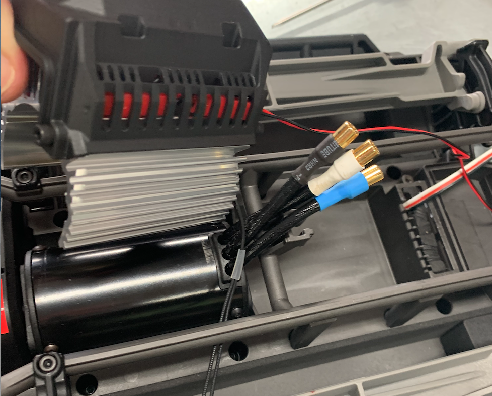
Put the ESC into the chassis in the place of the old ESC.
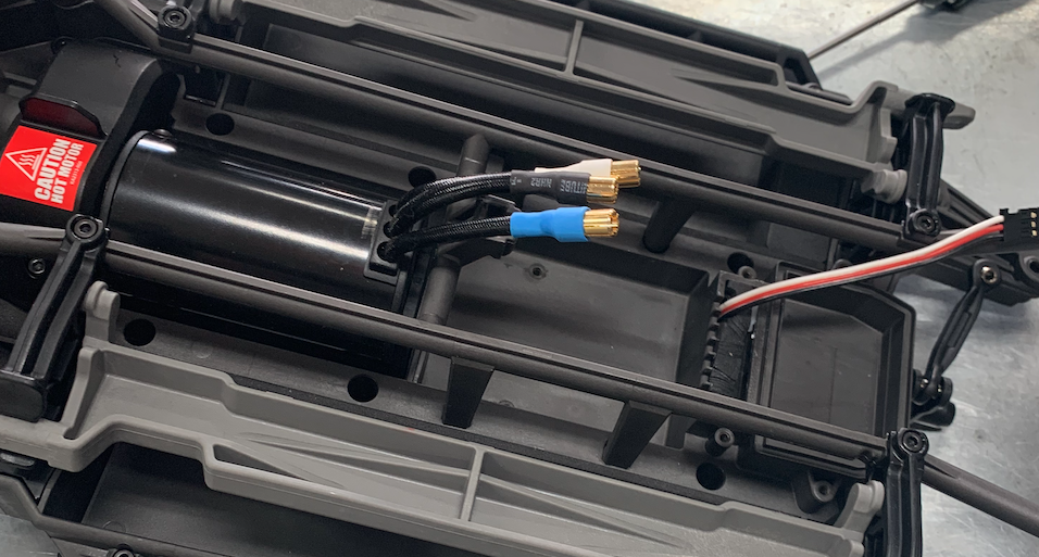
Gold connectors at the motor side.
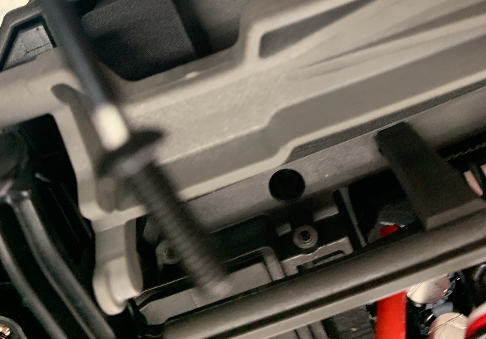
Put is as far as possible to the front but leave 1-1,5 mm free for the cables at the front. So there is a lot more space at the back than at the front.

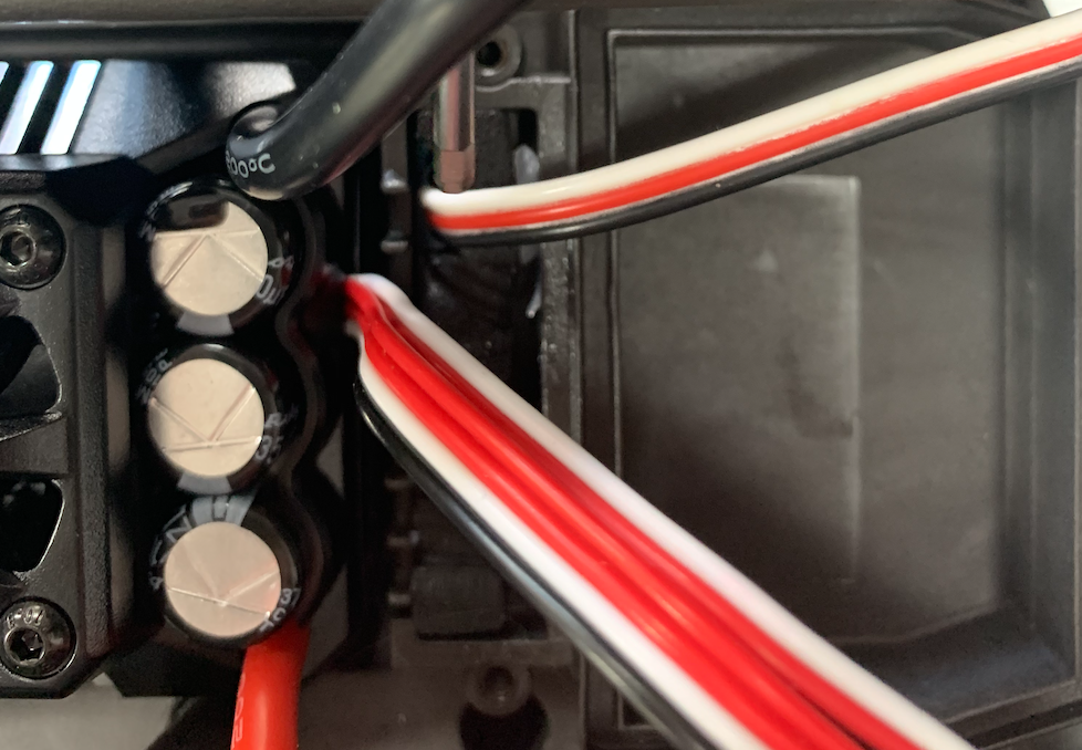
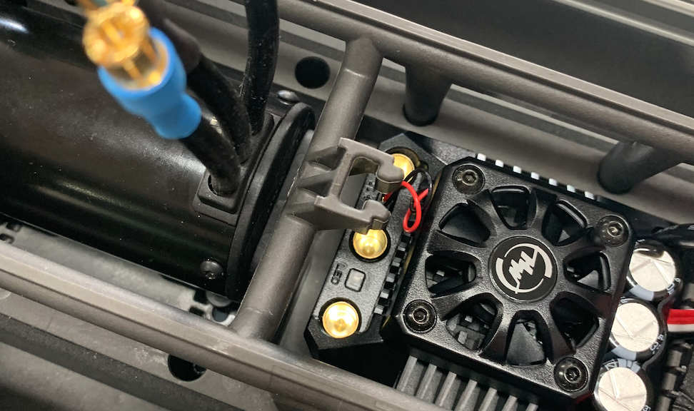
Put the motor cables in place.
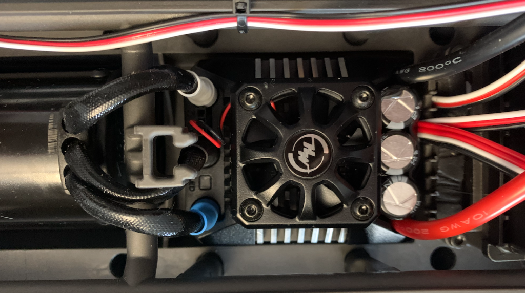
Stick the other tape to the on/of button
Oke, lets put it together.
Put the chassis upside-down.
Slide the from into the back.
There might some resistance from the main axis. The sprocket has to fit. Try to turn the axes of both front wheels.
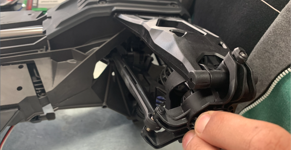
And press until it fits.
Put the screws back.
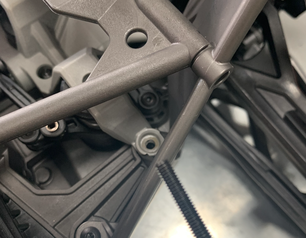
Connect the steering rod.

I think the only thing left is replacing the cover with the sensor.
This might take some time, the sensor might be a bit to wide. Then you need to push it in place.
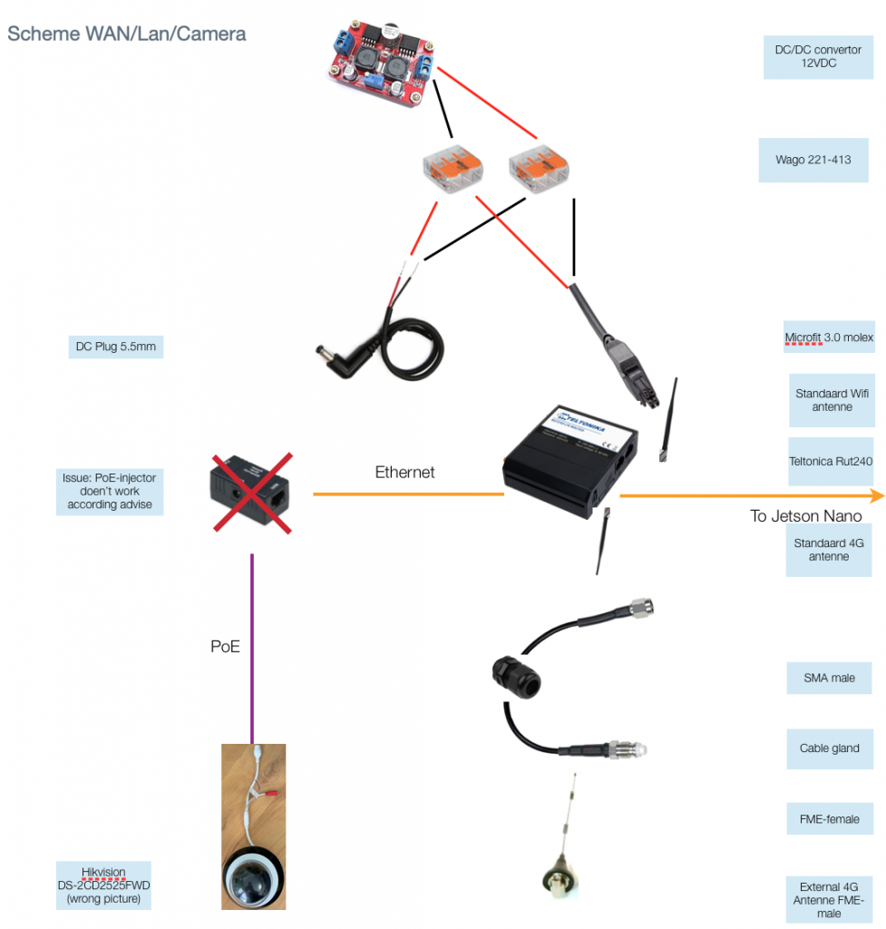
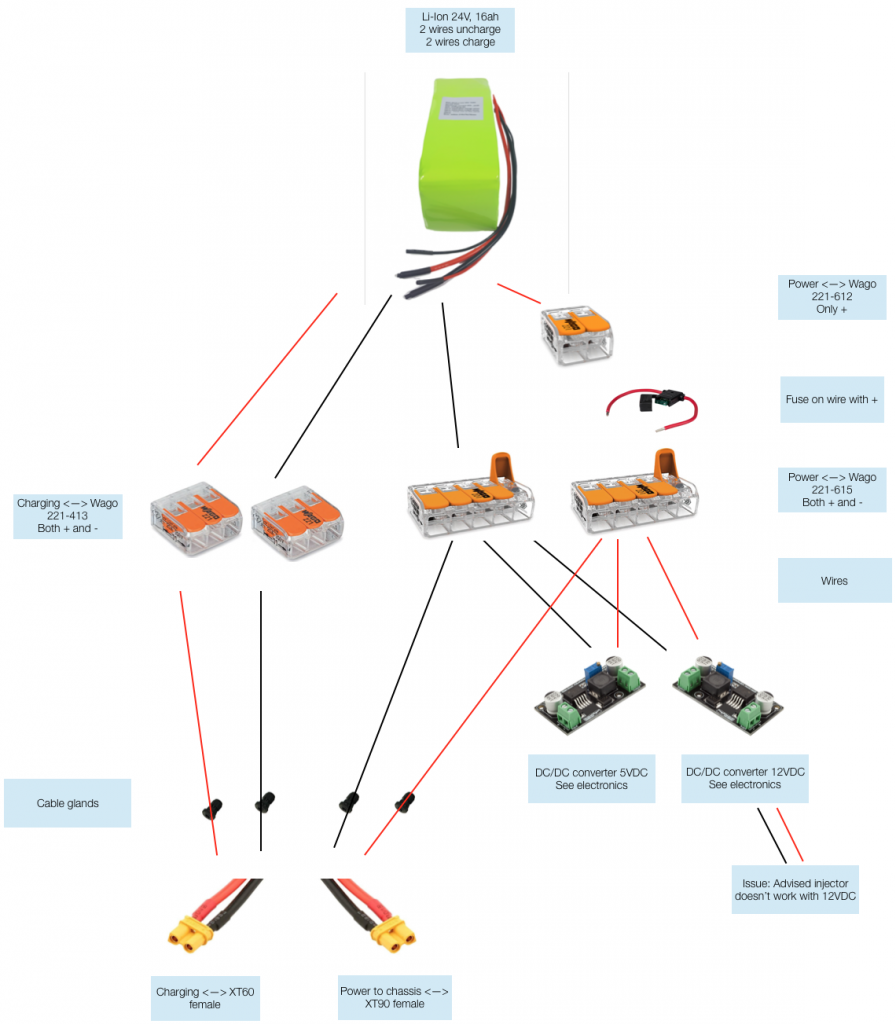
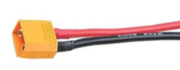
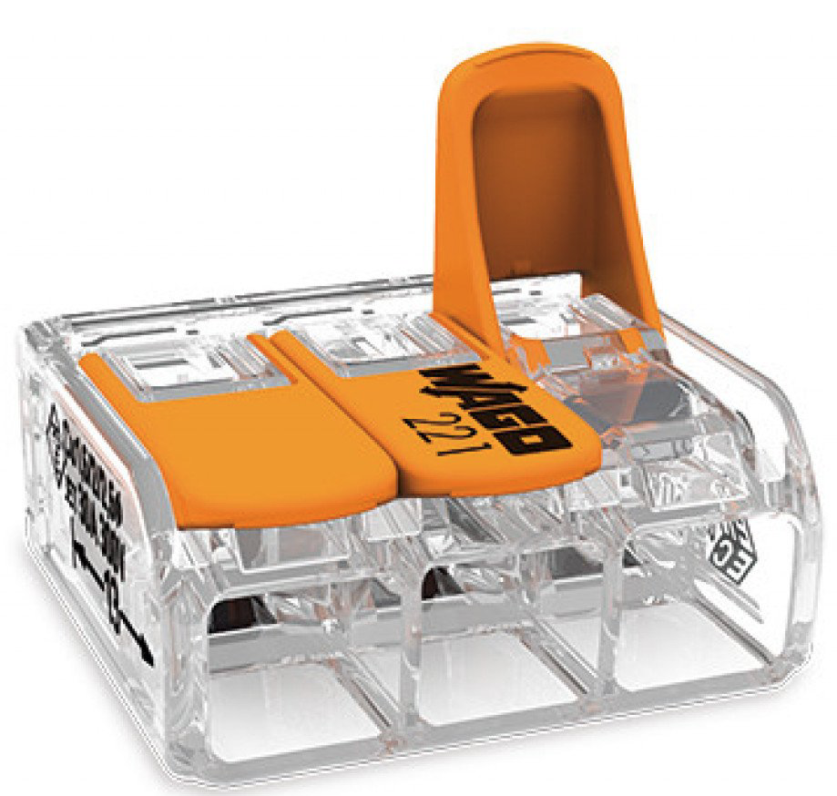
The connector on the ESC must be connected to the power supply. To do this and avoid soldering, a wired XT90 male can be coupled to the wires on the ESC using two Wago 221-612 connectors.
Oke, that’s it. As I said, if you do this for the fist time, it can take several days.
0.1-200408 First version
Het Corona virus is de grootste bedreiging voor mensen die opa of oma zijn of hadden kunnen zijn.

Het is belangrijk dat deze ouderen voorzien worden van hun dagelijkse levensbehoefte en medicijnen.
Deze moeten bij hen gebracht worden.
>> Introduction / Content
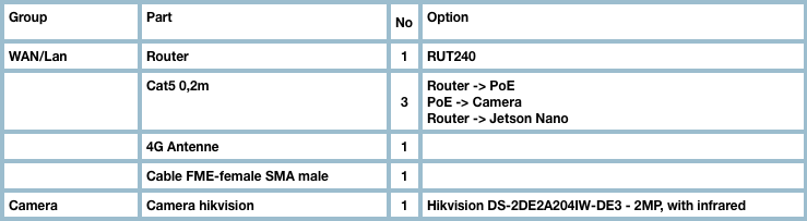
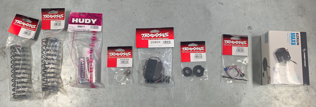
We are working to assemble robots and give them away to those who can use them. The parts for this don’t have to be new. The following parts are needed:
There is als a lot of work to be done:
0.1-2003270918
My friend Massy asked me to make available all the knowledge we developed in building our test robot. He convinced me that in our current situation, the robots might be very useful to deliver shopping for people who can’t leave their house for instance
So I agreed to give this a try.
If you think that some solutions are not very handy, I guess you’re right. I’m just functional architect for software systems. Robot hardware is new for me.

But lets start.
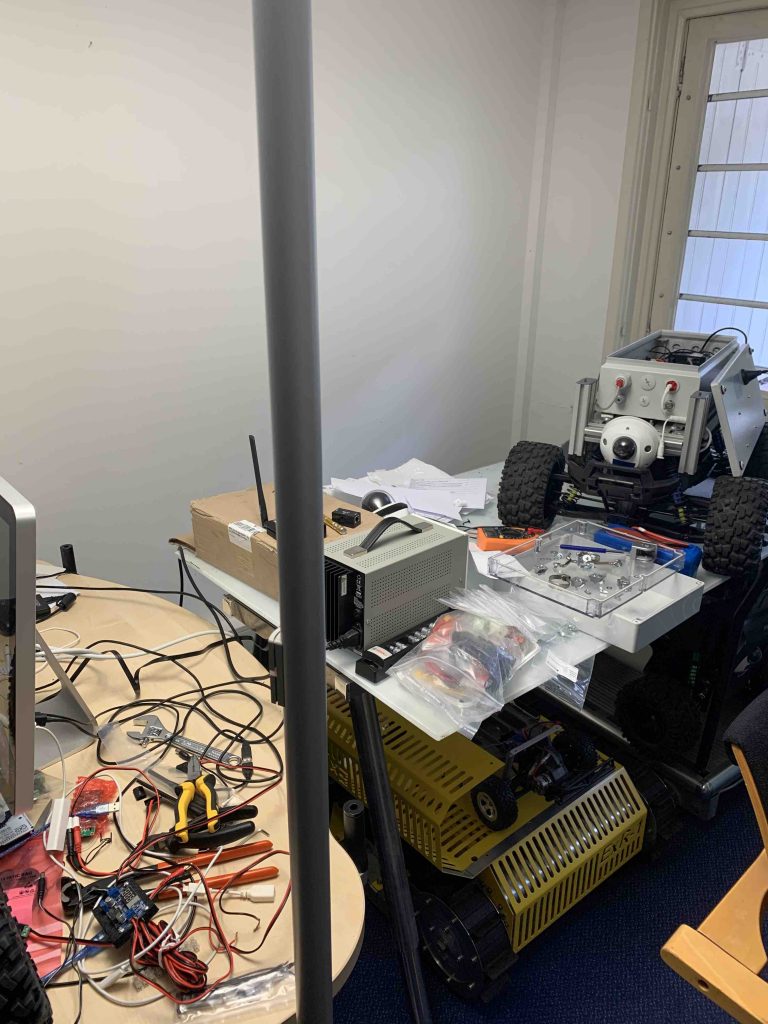
I cleaned up our workshop, so the table is free to make pictures and to show the steps to build a robot.
At the end you should have a small, personal, self driving robot. This robot should be able to operate as autonomous robot to pick up and deliver groceries and medications without the need for physical contact.
I’m going to show how we make our robot as an example. When you built one you can use the software from MWLC, the company I work for, for free as long as it is for your personal use and you don’t use it for commercial purposes. For any commercial, educational or professional use you should get the appropriate, paid license from MWLC.
You can control the robot via internet and have it autonomously driving straight roads and simple turns.
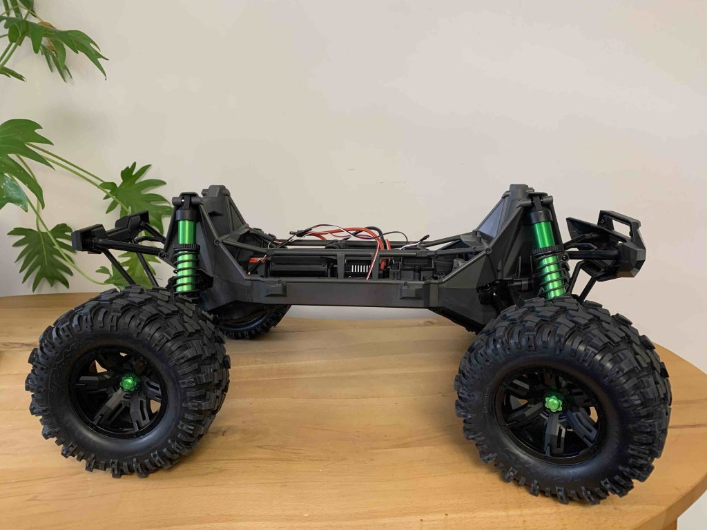
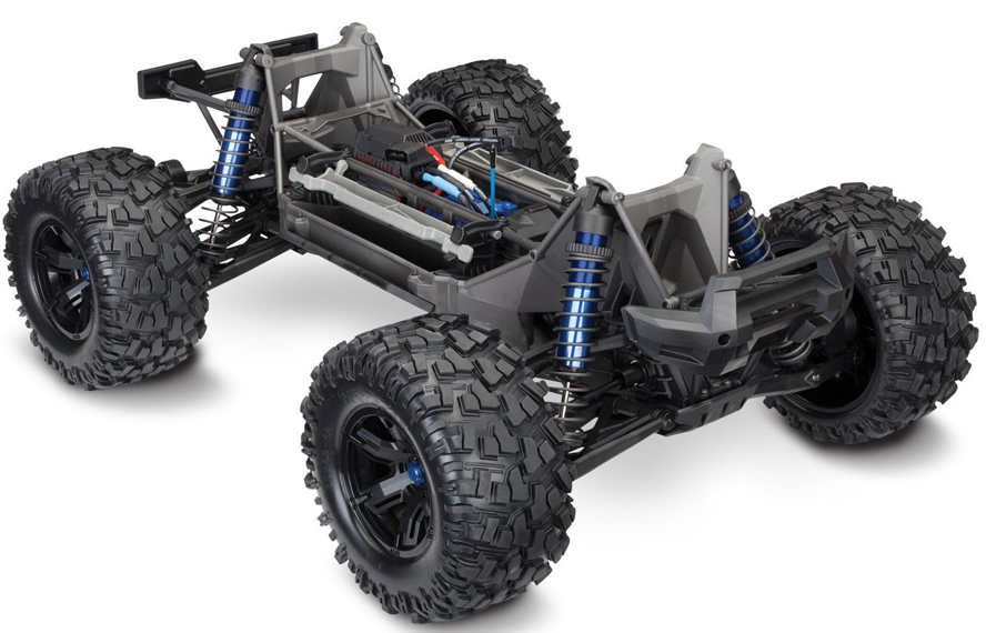
In my example I start with a Traxxas X-Maxx. Of course it is also possible to use other RC cars. The makeover is done in 5 stages (see: Content) and is reversible:
This is an example. Don’t hesitate to improve it or reduce the cost with alternative parts. Some parts are necessary for the software:
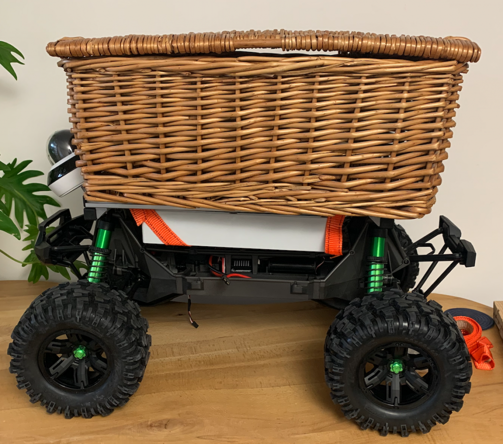
We shall end up with something looking like this:
Lots of people will recognise this.
Just missing the red hood.
Next step: The tools
0.2-2004011138 all over
0.1-2003262009
Dagelijks krijg ik persoonlijke waarschuwingen uit Berlijn van een vriend die studeert in Berlijn en bij het zelfde instituut zit als een van de grootste deskundige op het gebied van Corona-virussen. Er wordt mij op het hart gedrukt dat de situatie in Bergamo(21 maart ’20) ons voorland is.
Voor mensen die over de zeventig en tachtig zijn wordt de komende tijd er één van leven of dood is. Meer mensen zullen geïsoleerd raken of met gevaar voor eigen leven, aan hun spullen en levensmiddelen moeten komen. Mensen in de risico-groepen zijn er overal ook hier, ook in mijn eigen familie.
Ik ben bestuursvoorzitter van de Ofoundation en werk veel samen met een bedrijf, MWLC, dat autonome robots ontwikkeld. Zij hebben een prototype robotje in hun lab dat zelfstandig goederen kan vervoeren. Dit robotje is niet af.
Van het bedrijf heb ik toestemming om de gegevens over dit robotje voor een zelfbouw versie vrij te geven. Ik heb ze overtuigt om, voor wie een robot bouwt, ook de software beschikbaar.
Ik weet niet of het robotje voor iemand iets gaat toevoegen. Maar als achteraf blijkt dat het wel zo was, is het te laat.
Met het robotje kunnen boodschappen en medicijnen opgehaald en gebracht worden voor wie het nodig heeft. Het kan tot 10 kg dragen, voldoende om iemand voor 3 to 4 dagen van de eerste levensbehoefte te voorzien. Het robotje kan tientallen kilometers per dag rijden en is aan te sturen is met een een controller van een oude spelletjes computer. Het is slim genoeg om een route langs landwegen en eenvoudige bochten, zelfstandig af te leggen.
Ik nodig iedereen uit naar het ontwerp te kijken en het te gebruiken.
Op deze website vind je de tekeningen en uitleg hoe je zelf zo’n robot kunt bouwen uit een speelgoed RC-auto en spullen van het internet. De robot is klein en ongevaarlijk maar heeft wel hulp nodig.
Het ontwerp van deze robot vind je hier en bij de inhoudsopgave. Het voorbeeld is gebouwd en getest.
Het is niet af.
Als je een technicus bent, handig met computers of wat vrije tijd hebt om een robotvoertuig te besturen, kun je een bijdrage leveren. Aarzel niet om het ontwerp goedkoper en beter te maken. Geef reacties onder aan de pagina’s.
Wat is er nodig? Bijvoorbeeld:
Het ontwerp is gratis.
Neem contact met op info@projectroodkapje.nl voor de software en de verbinding met de cloud zodat je de robot kan laten rijden.
Het gebruik van de software is gratis, zolang het, in welke vorm dan ook, niet wordt gebruikt voor commerciële exploitatie of professioneel gebruik.
Op verzoek van enkel lezers zet ik met google translate de website om naar engels.
Ken je iemand die kan helpen, geef dan de link door.
Bedankt,
Massy Wahab
Every day I receive personal warnings from Berlin from a friend, who studies in Berlin and works at the same institute as one of the greatest experts on Corona viruses. I am urged that the situation in Bergamo (March 21, 20) is our foreland. For people who are over seventy and eighty, the coming period will be one of life or death. More people will become isolated or will have to get their belongings and food at the risk of their own lives. People in risk groups are everywhere, here and in my own family.
I’m member of the board of the Ofoundation and have a good connection with a company, MWLC, that develops autonomous robots. They have a prototype robot in their lab that can transport autonomously goods. This robot is not finished.
I have permission from the company to release the data about this robot for a self-build version. I convinced them to also have the software available for those who build a robot.
I don’t know if the robot will add something for someone. But if it turns out afterwards that it was, it is too late.
With the robot, groceries and medicines can be collected and delivered for those who need it. It can carry up to 10 kg, enough to provide someone with the basic necessities for 3 to 4 days. The robot can drive tens of kilometers per day and can be controlled with a controller from an old game computer. It is smart enough to cover a route along country roads and simple turns independently.
I invite everyone to look at the design and use it.
On this website you will find the drawings and explanation how you can build such a robot from a toy RC car and stuff from the internet. The robot is small and harmless, but it does need help.
You can find the design of this robot here and at the table of contents. The example has been built and tested.
It is not finished.
If you are a technician, handy with computers or have some free time to drive a robot vehicle, you can contribute. Don’t hesitate to make the design cheaper and better. Leave comments at the bottom of the pages.
What is needed? For example:
The design is free.
Contact info@projectroodkapje.nl for the software and the connection to the cloud so that you can let the robot drive.
The use of the software is free, as long as it is not used in any form for commercial exploitation or professional use.
If you know someone who can help, please provide the link.
thanks,
Massy Wahab
0.1-2003261944
>> Introduction / Content
Here you find an overview of the tools I used until now. If there is a change I will provide an update asap.
It should be as easy as possible to put a robot together. So:
– All parts should be available via internet without tailoring
– Soldering should not be necessary
Until now this works for us, but it does mean that some parts can be cheaper if you are handy with soldering and are skilled with a hacksaw.
If you are patient enough, there aren’t a lot you tools you need beside the tools that come with the x-maxx. But I’m not that patient. So I used:
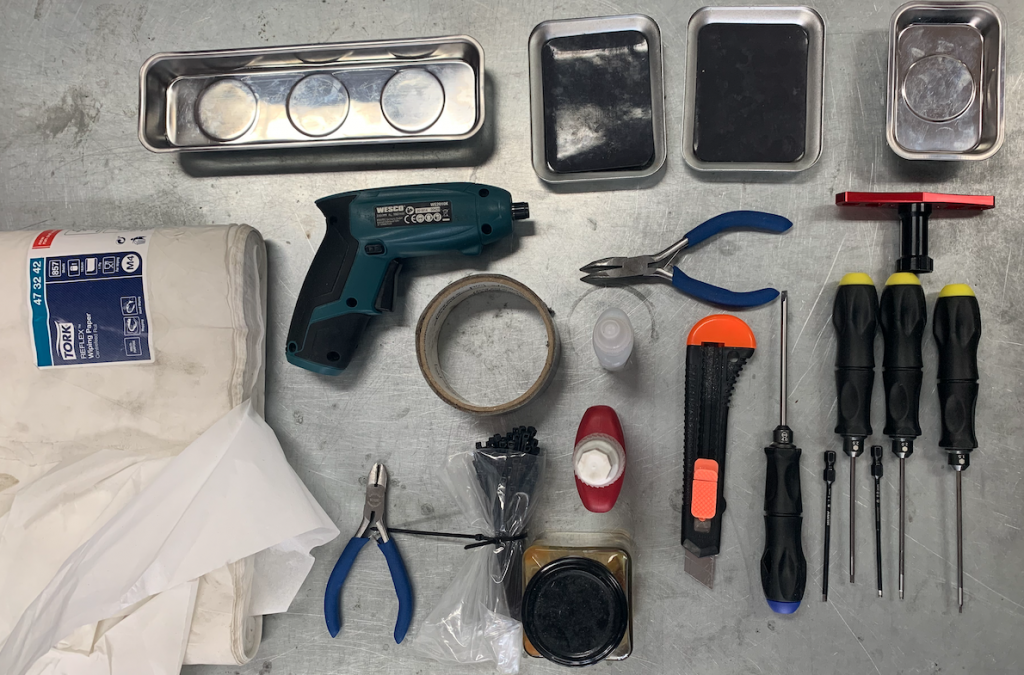

With this tool set I didn’t do the makeover of the x-maxx chassis. The necessary tools are mentioned in the video’s.
I have to confess that I asked the retailer to put it together.
For the next robot I will do it myself and explain how this works.
For now the next step: The frame, enclosure and connections
0.3-20040615:51 Tools for the chassis
0.2-2004011310 new tool set
0.1-2003271322
>> Introduction / Content

The telemetry sensor doen’t always work as expected. The sensor might not give a signal. This is strange, knowing that we used the same part numbers in all cases. The way to solve this is drilling a 5mm hole, through the cover and take some of the material off the cover away with a bigger drill. The sensor should fit into this space. We will show pictures asap.
Below are links with examples. There is no specific preference for the suppliers.
In principle, it does not matter which vehicle is used as the basis.
The Traxxas x-maxx 8s is taken as an example because there is knowledge available about how to make it drive using digital instructions and it can carry some cargo. However, in principle, any vehicle can be used if it is drive by wire.
The 8s is the largest Traxxas model, but much too fast and with minimal carrying capacity. To be able to carry more cargo, the vehicle must be converted so that the motors for steering and driving last longer.
For more information about the Traxxas, also see the relevant YouTube channel. You can search for the x-maxx there.
The makeover is done in two main groups of activities:
The change of the x-maxx is reversible. If you are ready these parts are left over:

Especially not in the plastic.
Using a drill will apply too much force. So stop immediately if a screw gives resistance.
Now, take off the body and the wheels.
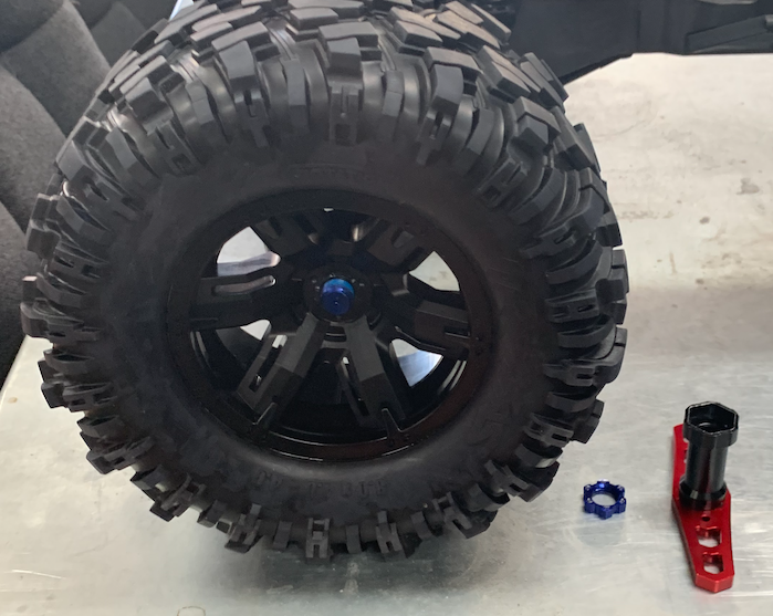

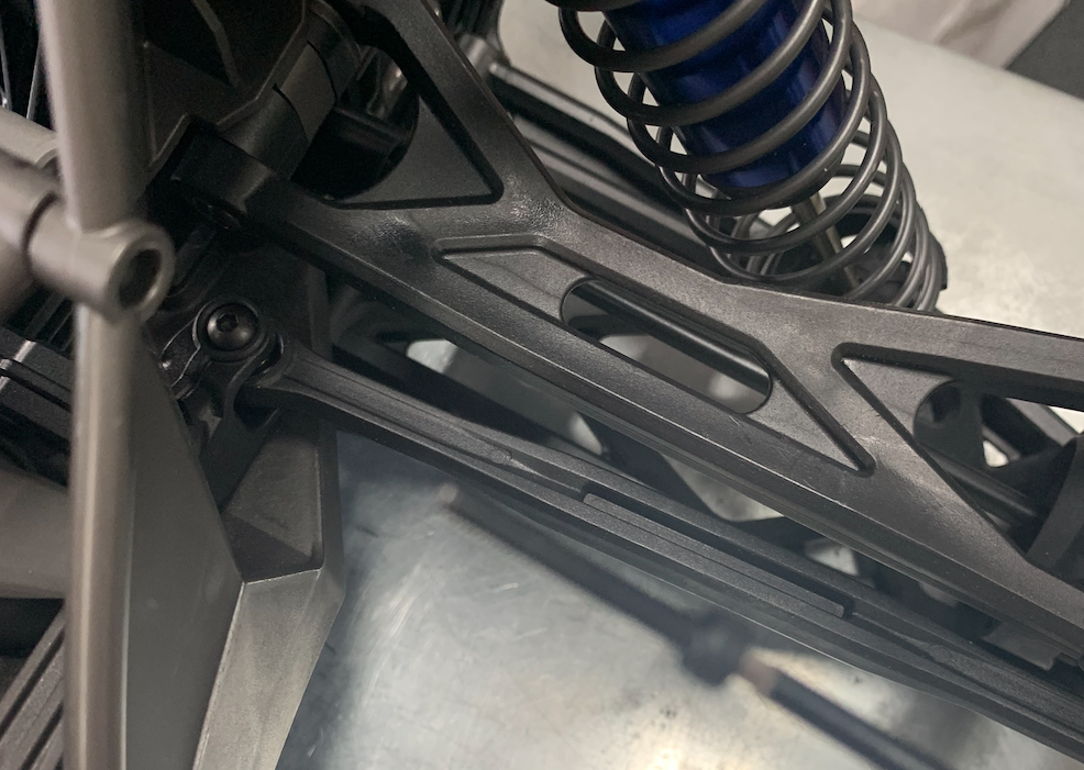
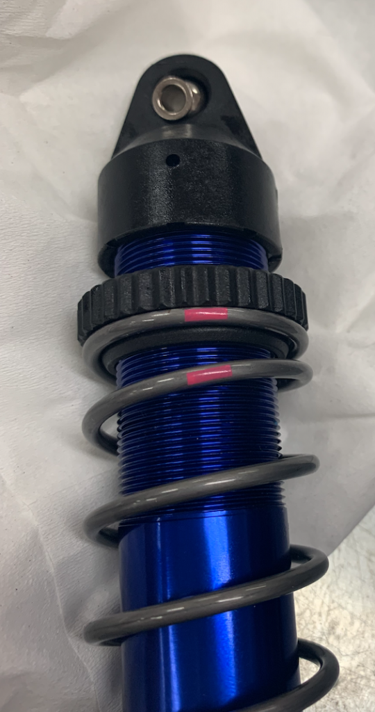
Strong springs are needed. The strongest springs available from Traxxas are enough for loads up to about 2-6 kg, depending on the number of batteries on board.
The spring rate is just over 1.5.
Stronger springs are desirable.

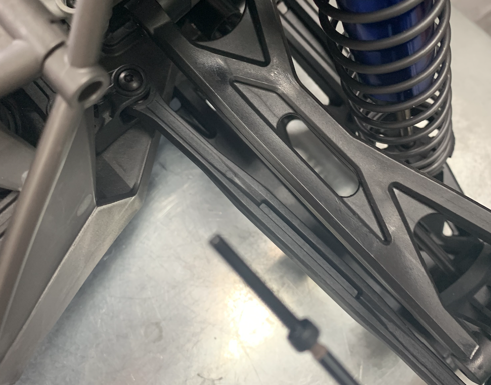
The shock absorber oil should be much more viscous than the standard oil. The syrupiness can be expressed, among other things, in cSt (centistoker). We use 1,000 cSt in the shock absorbers.
Example
For the replacement of the shocks’ oil and suspension springs there are several videos on the internet. There is a Traxxas shock and suspension maintenance video.
This one looks fine for replacing the suspension and oil.
Some differences:
Note:
There is nothing special to mention here. Just follow the instruction on the video.
When done move on to the next stage.
0.6-2004111255 Issue with sensor, spur is off parts list
0.5-2004081538
0.4-2004061732 New description
0.3-2004061628 Spur in review, other Wago-connectors
0.2 2003281657 Video example ESC
0.1 2003262346