>> Introduction / Content
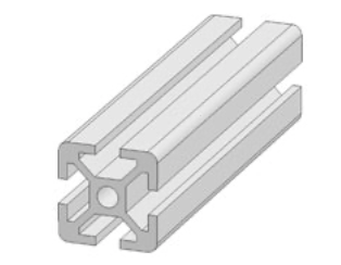
The beams are aluminium profiles, 20 x 20 mm with groove 5.
4 beams are used, two crossbeams and 2 longitudinal beams. The longitudinal beams rest on top of the cross beams.
The length of the crossbeams should equal the outside width of the enclosure added to the width of the longitudinal beams. In the example the width of the enclosure is 23 cm, so the length of the crossbeams should be 27 cm.
The crossbeams
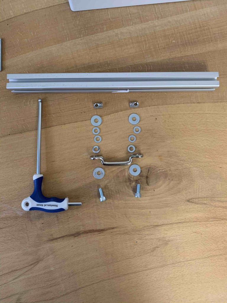
Connect tie down strap eye to crossbeam

Slide the two sliding blocks into the groove of the crossbeam.
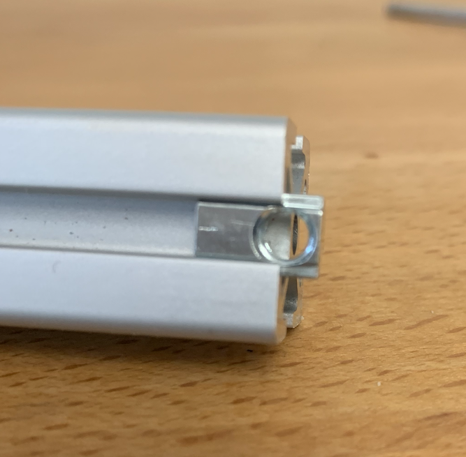
Attention! These are the M5’s.

Take the Allan screw, M5- length 12, some big and small washers and the tie down strap eye.
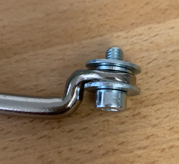
Put them together to turn the screw in the sliding block.

Connect the strap eye to the crossbeam.
Depending on the distance between the strap eye and the plate on the chassis you can use one or more small washers between the strap eye and the crossbeam.
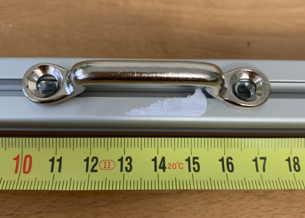
The middle of the strap eye should be in the middle of the crossbeam.
Connect crossbeam to chassis
You now can connect the crossbeam with a hose clamp to the chassis.

First put the hose clamp around the chassis and through the strap eye.
Turn the hose screw so the clamp is connected and starts to engage again.
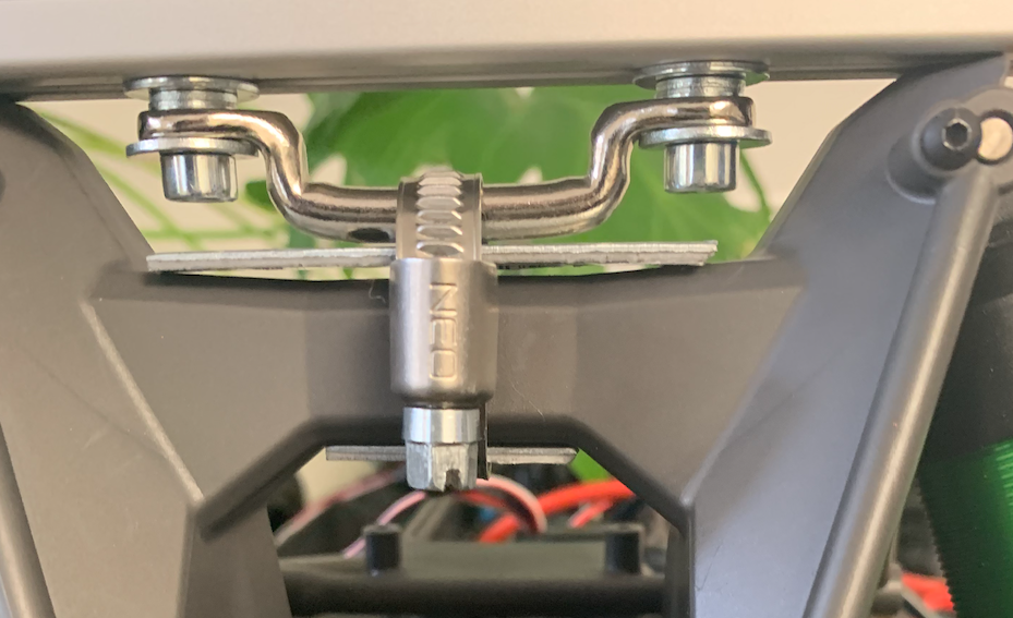
Put the top and bottom plates on both sides of the chassis-beam, between the hose clamp and the chassis.
The distance between the strap eye and the top plate should be enough to avoid too much pressure on the chassis-beam. The chassis-beam might break.
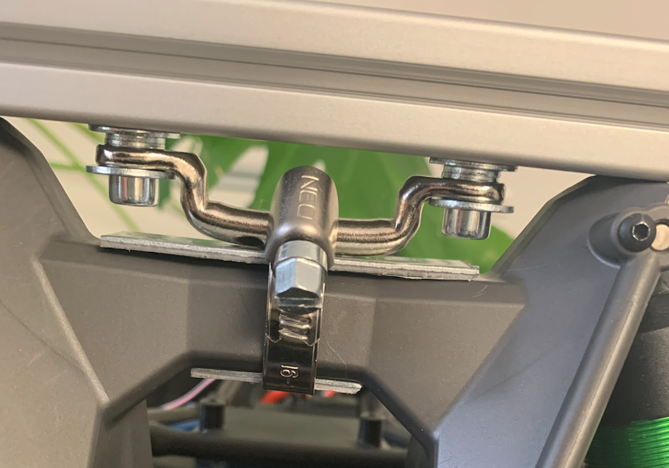
Tighten the hose clamp screw to fix the crossbeam to the chassis, but not to tight yet. We need some flexibility to attach the longitudinal beams.
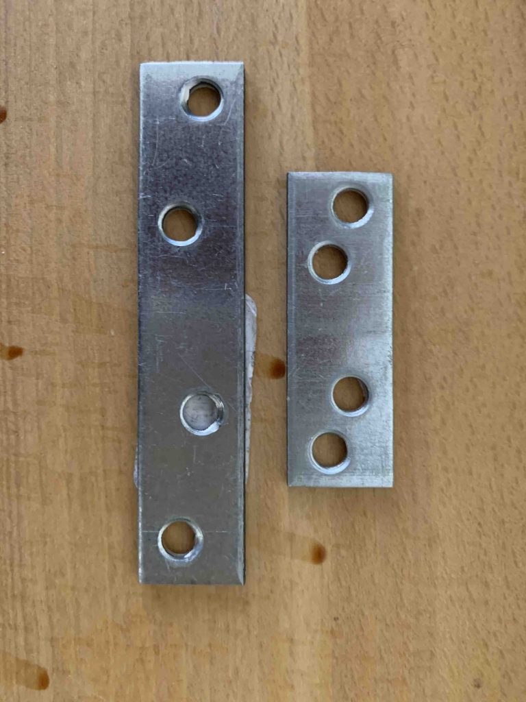
Size of top plate front: around 62*15*2 mm
Length of bottom plate back: around 3 cm
Length of top plate back: around 66*15*2 mm
Length of bottom plate back: around 45*15*2 mm
Thats it, on to the next step.
The longitudinal beams
The length of the longitudinal beams depends on the length of the vehicle. In our case, the x-maxx, 47 cm is enough.
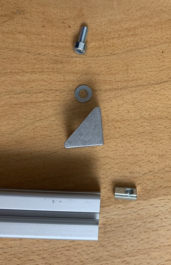
To attach the longitudinal beams to the crossbeams, connect a corner bracket to each end of the longitudinal beams. Use an Allan screw size M4 * 10, a sliding block size M4, a washer size M4 and a bracket.
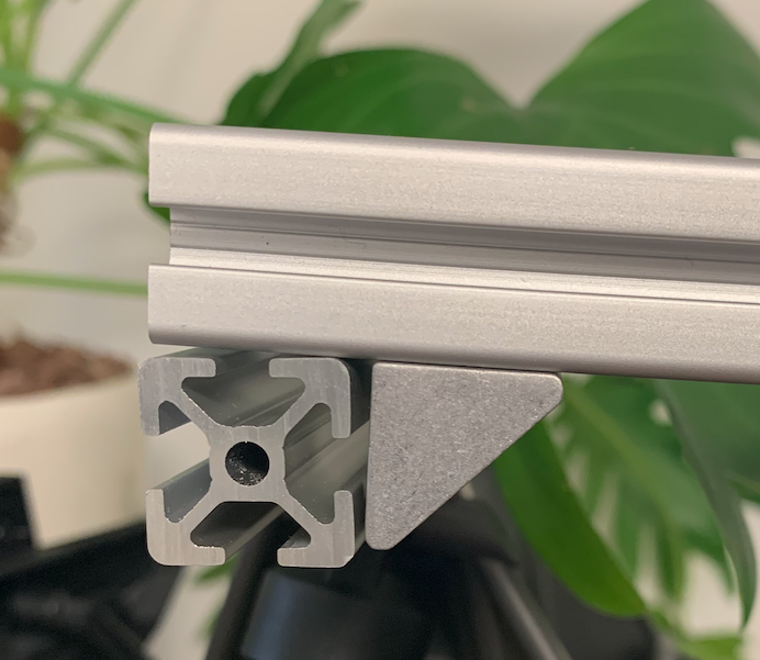
Put the sliding block in the groove.
Take the Allan screw, and the washer and screw the corner bracket to the profile.
The bracket should be 2 cm from the end of the profile.

Put four sliding blocks into the groove of the crossbeams. One at each end.
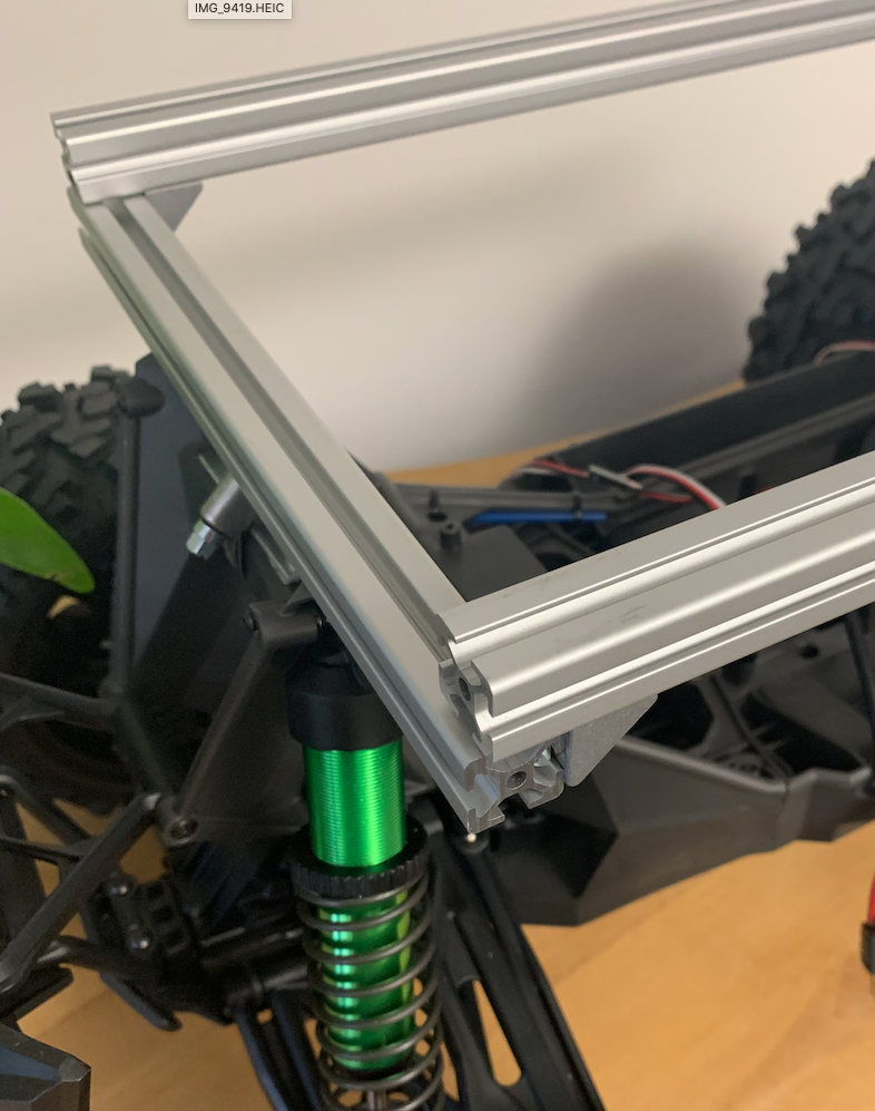
And take four Allan screws and washers and screw the bracket on the longitudinal beam to the crossbeam.
Knee connector for camera
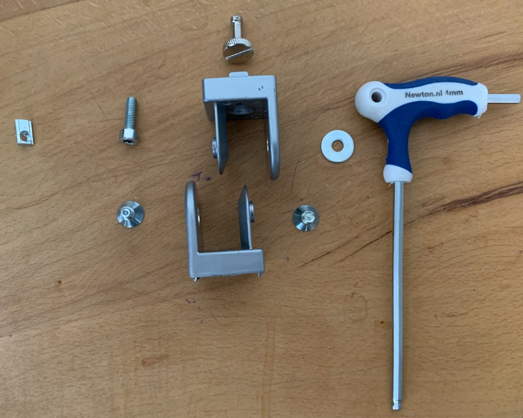
Take the knee connector, an Allen screw M5*16, a large washer and a sliding block M5.
Put the sliding block in to the groove. This doesn’t have to be done from the side. You can put in anywhere along the groove.
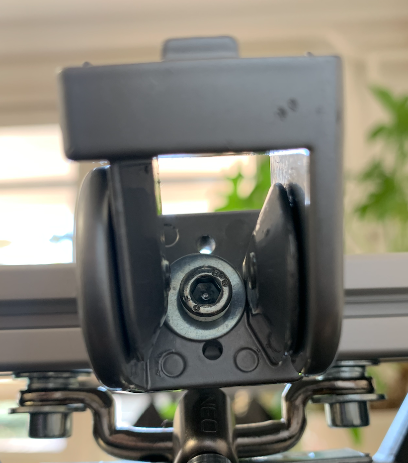
Connect the knee connector to the crossbeam.
In my case the knee connector has two little protruding bits that didn’t fit in the groove. I used a file to make these a bit smaller to fit into the groove.
There are knee connectors available that fit without the need to file but for those its difficult to find a fitting camera screw.
Beam-end covers
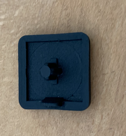
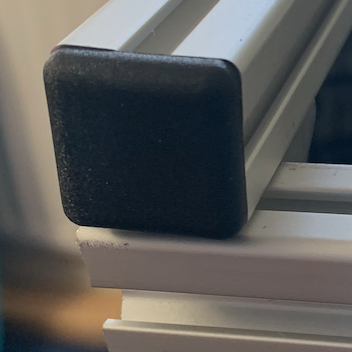
Take the beam end covers and put these on all 8 ends of the four beams.
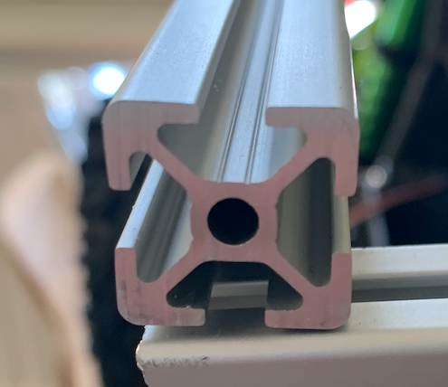
That it for the frame.
0.4-2004031205 change to bigger knee joint
03.-2004021203 knee connector covers
0.2-2004012033 Details beams
0.1-2004011711 Details added
